Simple Radio Remote Control
Transmitter and Receiver
 Image 1: Remote in use at Midsouth 2023 Fall Meet Here you see the transmitter being used to operate the "Powered Gondola" 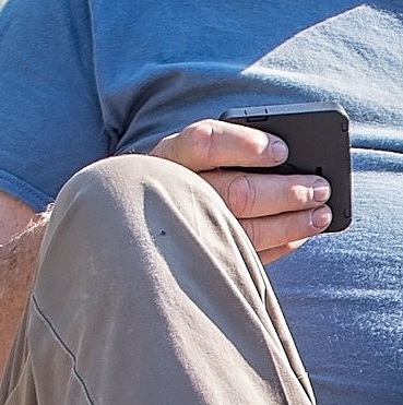 Image 2: Size Comparison This little transmitter is three inches square and about 3/4 inches tall. 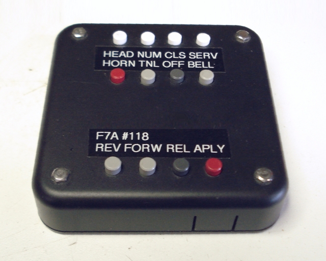 Image 3: Simple Pushbutton Controller Twelve buttons, each transmit a unique 4-bit code on a 315 Mhz carrier using On-Off Keying (OOK). It is up to the receiver to decide what to do with the codes received. There is NO 10K pot! 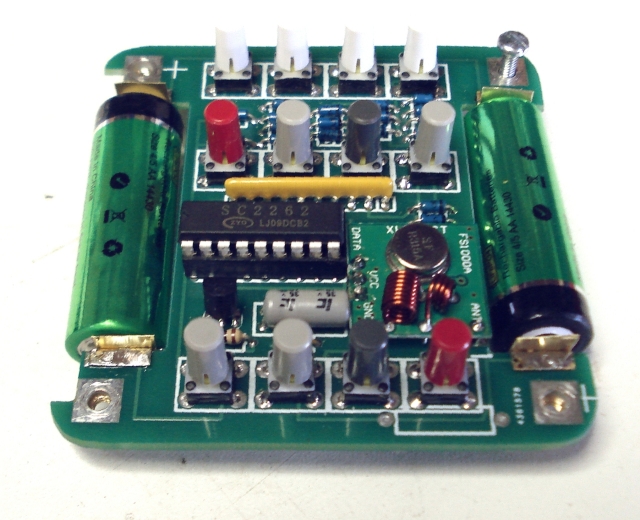 Image 4: Circuit Board Topside From the circuit board topside, several components are obvious. The batteries can be considered "permanent". Because they are large, the current demand is low, and they likely will never need to be replaced or charged, so there is no need to do either. 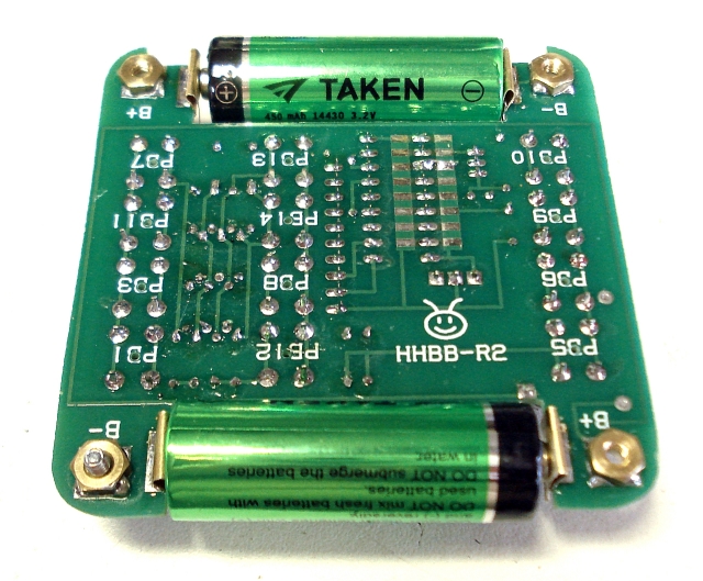 Image 5: Circuit Board Bottom side The bottom side of the board can be seen when you remove the box's bottom cover. If you look carefully, you can see the antenna. It is the PCB trace running completely around the component area. You can also see the brass mounting nuts soldered to the underside. The only other prevailing feature is the programming area. 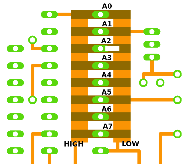 Figure 1: Jumper Programming Area The radio address can be set to one of 6561 unique addresses, in case you have more than one receiver or there are others at the track with similar radios. Eight address inputs can be tied low or high or left unconnected. Each combination of low, high, or open generates a unique address. In the photo above, address A2 is tied low. When asked what your address is, you can say "A2 low" or whatever your combination is. Tie an address pin low by bridging it to the LOW bus, or tie it high by bridging it to the HIGH bus. (But don't do both.) You can bridge by using a solder bridge or a piece of wire. I use the wire method.
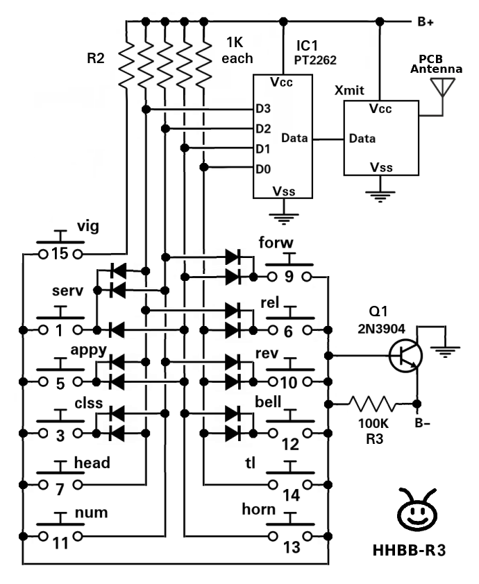 Image 6: Simplified circuit board schematic The 4-bit data is diode encoded as follows...
Obviously, pressing other combinations will generate other codes which will be repeats of previous codes. It is up to the receiver decoder to decide what to do with the codes as they are received. "flip codes" exist and are used when the bit order (D3:D0) is reversed from what is needed. This is caused by various issues including which receiver module is used in the application. Receiver vendors can't seem to agree on bit order. I have begun laying out my PCBs so that the receiver module can be plugged into the board with either bit positioning. Simple Remote Receiver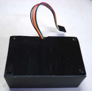 Image 7: DinoBox Receiver "DinoBox" was designed to connect directly to a "DNO" series power controller. It can work with others as well. It is pin compatible with the controller and is also powered by it so no other connections are needed. Although it decodes all code combinations, it only uses motion control commands, Forward, Reverse, Accellerate, Decellerate, and Stop. An output extension is available to connect a variety of other accessories such as a Horn, a Bell, Train Line, or Lamps. 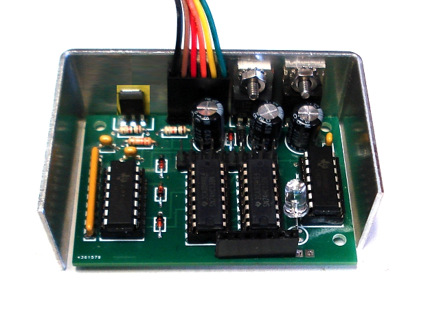 Image 8: DinoBox Internals The receiver module is not shown in the photo. It plugs into the inline connector at the bottom. The center two integrated circuits are decoders that split the 4 command lines into individual controls as follows...
The remaining two ICs are quad comparators used for the following,,,
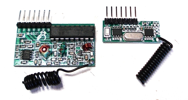 Image 9: Receiver Modules from Two Vendors In the photo above are two receivers. Both have 7 pin interfaces with pins that are labelled the same. The "purely analog" receiver on the left has a data order that is flipped from the "all digital" receiver on the right. The "analog" receiver has programming jumpers like the transmitter board. The "digital" receiver does not. It "learns" the address from the transmitter. The timeout timer will stop the train if a command is not received in 24 seconds. Any command will reset the timer. If no speed change is required, any passive command can be used to reset the timer. Example: forward, even if already in forward. etc. 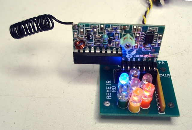 Image 10: Receiver Tester |