Image 157 -- Valve Timing
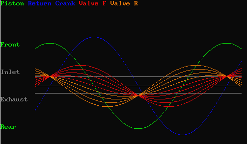
I am in the process of changing my basic valve timing. I don't like the way the current setup operates, and it's time to try something else. I have built up the right side valve gear, but now it's time to make a new valve piston for the right side. Below is a simulation of the "new" timing.
When a valve position line is above the "Inlet" line, the cylinder is open to live steam. When it is below the "Exhaust" line, the cylinder is open to the exhaust.
You can see in the "centered" valve setting, the valve piston travel is only influenced by the "lead" (a total travel of .389") and not by the return crank (a max travel of .75"). You can also see that in the centered position, the lead is not enough to open the valve to let the live steam into the cylinder. However, the exhaust side is set to open early, so the lead is capable of opening the cylinder to the exhaust.
I don't know how this compares to prototype practice, but this is what we are going to try next.

Pressure-Volume Diagram
(select diagram to visit image source page for details)
The diagram clearly shows that the inlet is not supposed to open until the piston reaches the very end of the stroke. Likewise, the exhaust does not open until the piston is at the other end of the stroke. This would not be possible if the lead exceeded the valve lap.
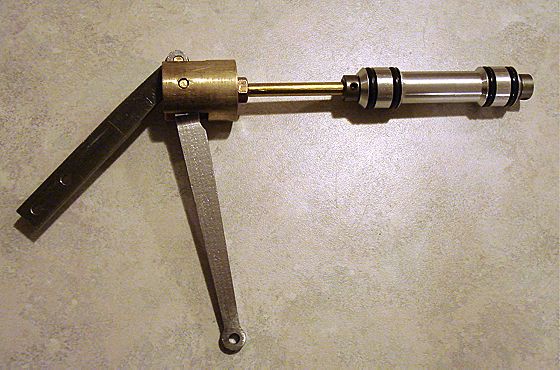
I have also done something I almost never do. I have gone back to the rod fastening method of the original drawings using collars pinned to the valve rod. This is necessary because it is not possible to guarantee perfect alignment between valve and crosshead. So the bore inside the piston is oversized to allow the rod to float.
12/31/7 Steam PipingJust got yet another 6 inches of snow today. That makes this a record December. Time to do some steam piping. Today I think I'll hook up the brake cylinder and the blower pipe.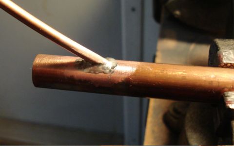
Image 139 -- Joining the blower tube to the main exhaust pipe (I love this picture) I have decided to join the blower into the main exhaust. This saves me from drilling another hole in the smokebox and makes assembly of the boiler and cab to the chassis alot easier. The blower tube goes up inside the exhaust tube about 3 inches and is soft soldered to the main pipe. 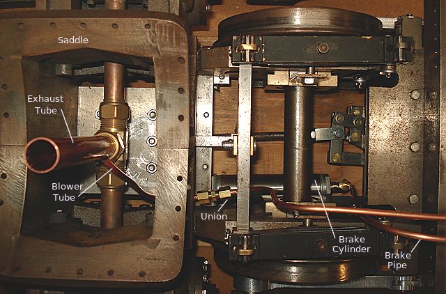
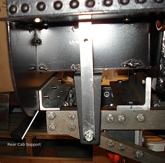
Image 140 -- Brake and Blower Piping Here I am back in the saddle again. The exhaust pipe is installed with the blower tube in it. A tube union makes it easier to thread the tubing under the saddle and up to the height of the boiler. A right angle pipe to tubing adapter is threaded into the brake cylinder and another tube comes up to boiler height for the brake line. Another set of unions will be used to join these to the tubes attached to the superstructure. |