-
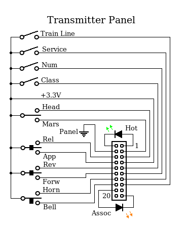
This is the switch panel for the Radio version of the handheld controller.
This connects to the transmitter board. I added an associate LED so I can
tell when it is in contact with the locomotive.
-
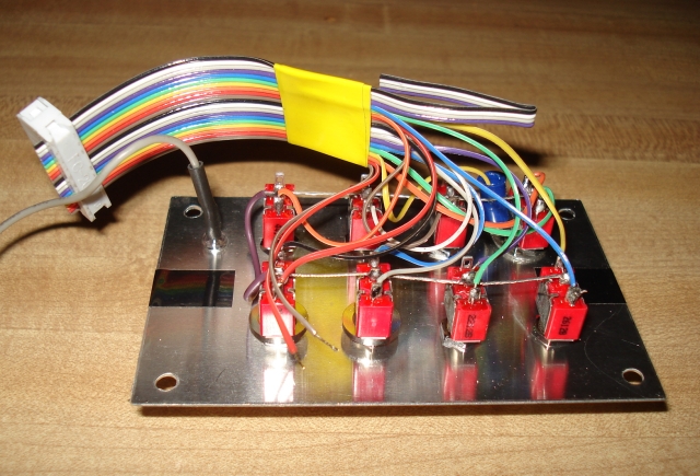
A photo of the back side of the transmitter panel.
-
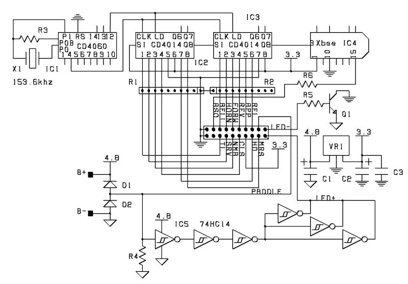
The transmitter board. Before I added the Associate LED, the Zigbee radio was
a three terminal device. Now it's four. Basically, the inputs from the switch
panel are serialized with the two CD4014 shift register ICs and delivered to
the transceiver module. The CD4060 divides the crystal frequency down to 9600
hz (the baud rate) and provides a load signal to the shift registers.
The gates at the bottom are for the power on/off function. They detect the
presence of a user and supply battery negative to the voltage regulator.
The receiver is in it's own box. It connects to the antenna via a coaxial cable
and to the LED and FPGA boards via ribbon cables. A multiconductor cable runs
between the LED board and the main relay box.
-
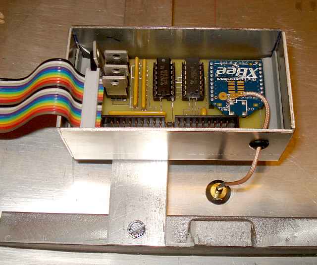
Note: The "receiver" and "transmitter" are actually both "transceivers". They
actually communicate with each other. Here you can see the "receiver" box
mounted to the inside of the steam hatch. Notice the antenna cable.
-
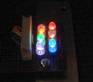
The LED board mounts in the rear window of the locomotive and is used to give
the operator status indication about the locomotive itself.
-
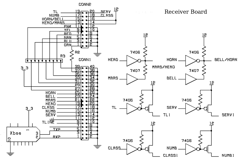
The receiver board is similar to the transmitter. It has two connectors. One
interfaces to the FPGA board. The other connects to the locomotive's relay box
and to the LED board mounted in the rear window. The gates on this board are
used to translate to signal levels required by the relay box.
 This is the switch panel for the Radio version of the handheld controller.
This connects to the transmitter board. I added an associate LED so I can
tell when it is in contact with the locomotive.
-
This is the switch panel for the Radio version of the handheld controller.
This connects to the transmitter board. I added an associate LED so I can
tell when it is in contact with the locomotive.
-
 A photo of the back side of the transmitter panel.
-
A photo of the back side of the transmitter panel.
-
 The transmitter board. Before I added the Associate LED, the Zigbee radio was
a three terminal device. Now it's four. Basically, the inputs from the switch
panel are serialized with the two CD4014 shift register ICs and delivered to
the transceiver module. The CD4060 divides the crystal frequency down to 9600
hz (the baud rate) and provides a load signal to the shift registers.
The gates at the bottom are for the power on/off function. They detect the
presence of a user and supply battery negative to the voltage regulator.
The transmitter board. Before I added the Associate LED, the Zigbee radio was
a three terminal device. Now it's four. Basically, the inputs from the switch
panel are serialized with the two CD4014 shift register ICs and delivered to
the transceiver module. The CD4060 divides the crystal frequency down to 9600
hz (the baud rate) and provides a load signal to the shift registers.
The gates at the bottom are for the power on/off function. They detect the
presence of a user and supply battery negative to the voltage regulator.
 Note: The "receiver" and "transmitter" are actually both "transceivers". They
actually communicate with each other. Here you can see the "receiver" box
mounted to the inside of the steam hatch. Notice the antenna cable.
-
Note: The "receiver" and "transmitter" are actually both "transceivers". They
actually communicate with each other. Here you can see the "receiver" box
mounted to the inside of the steam hatch. Notice the antenna cable.
-
 The LED board mounts in the rear window of the locomotive and is used to give
the operator status indication about the locomotive itself.
-
The LED board mounts in the rear window of the locomotive and is used to give
the operator status indication about the locomotive itself.
-
 The receiver board is similar to the transmitter. It has two connectors. One
interfaces to the FPGA board. The other connects to the locomotive's relay box
and to the LED board mounted in the rear window. The gates on this board are
used to translate to signal levels required by the relay box.
The receiver board is similar to the transmitter. It has two connectors. One
interfaces to the FPGA board. The other connects to the locomotive's relay box
and to the LED board mounted in the rear window. The gates on this board are
used to translate to signal levels required by the relay box.