Powered Tender TruckJanuary 31st, 2019
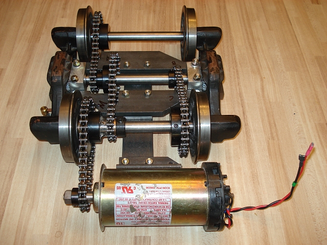
End view, inverted. The idler provides a means for coupling the motor (either overhead or behind the truck) to the common output shaft. It runs on one of the axles. This has some interesting advantages over a fixed shaft. First, it solves the problem of the axle being in the way and second, it distributes the wear on the axle. The idler is simply two sprockets welded hub-to-hub. Then the assembly is bored out on the lathe to accomodate a sleeve bearing designed to run on the 3/4" axle. This bearing has it's own lubricator as seen with the copper tube and oil cup. Probably not really needed with oil bearing sleeves. 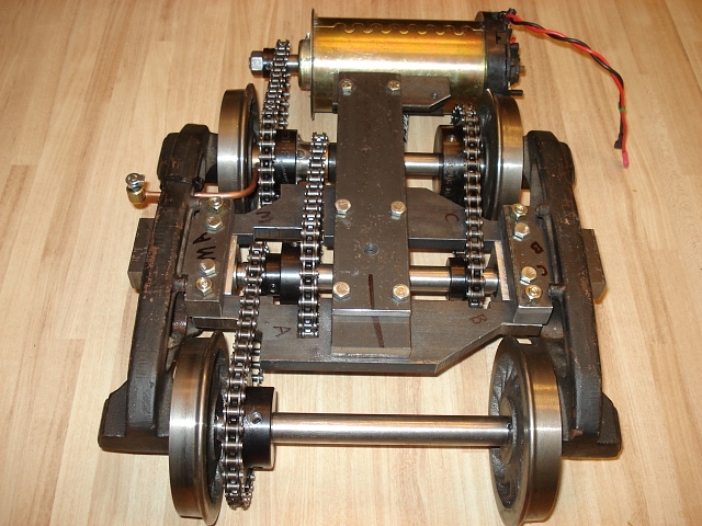
End view, topside. The output shaft bearing blocks are mounted on T shaped boltster bar ends which support most of the modified components.
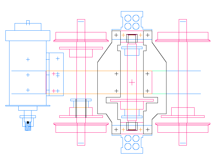
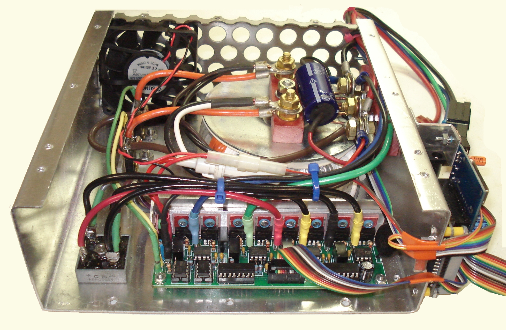
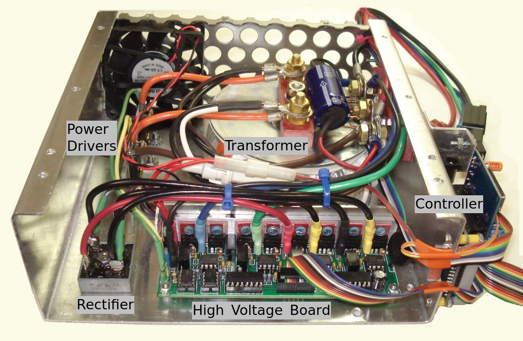
Top Down mechanical drawing of the truck and motor To power the electric motor, a special power supply (called a DC to DC converter) is needed. Shown below is the power supply for the tender truck. It requires 24 volts DC and generates up to 120 volts DC for the motor at up to 1100 watts long-term and much more short term.
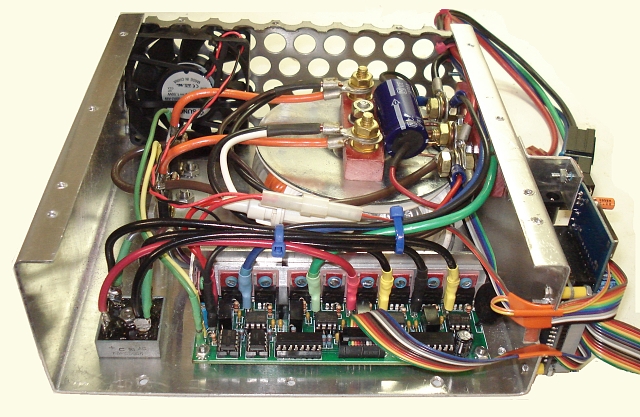
Tender Truck Power Supply View a larger photo HERE
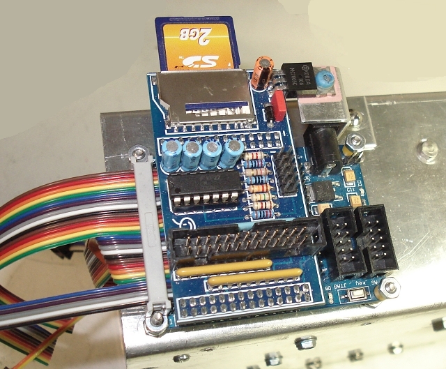
Tender Truck Power Supply Controller The power supply is controlled by this small stack of boards. The lower board is a basic Altera FPGA breakout board. The upper board is the I/O interface between the power supply and the FPGA board. The firmware for the controller can be loaded from the SD memory card at powerup. Bill
|
-