Steam Locomotive -- page 12(Back to Page 11) - 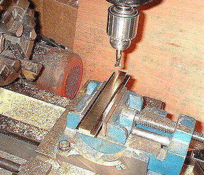
image 44: Crosshead Bearings Another fun part to make are the crosshead bearings. This again is alloy 954 aluminum bronze. This piece will be cut in half to make two bearings. Some precision is required here. - 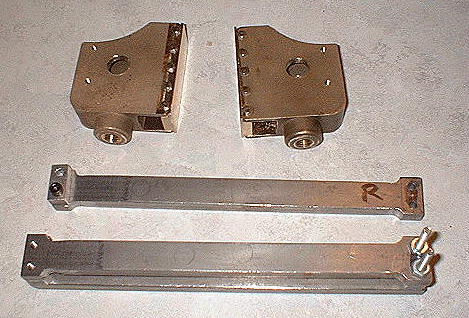
image 45: Crosshead, Bearings, Guides, and Slides Here are the completed crossheads, drilled, tapped, assembled. Also shown are the crosshead guides (or part of them). - 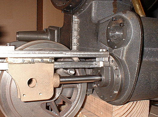
image 46: Piston Rod, Crosshead, and Guide It is a real challenge to get this to work right. Everything must line up perfectly or the piston or rod will bind up. The slide must be a precise height above the rod and must be parallel to it. The slide must be precisely inline with the cylinder walls as well. - 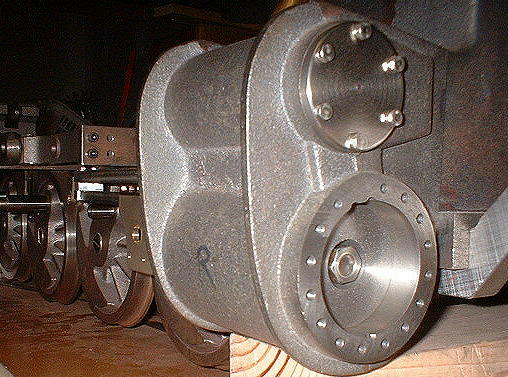
image 47: End of Piston in Cylinder Now here is a really close fit. The cylinder is 2.251" in diameter and the piston is 2.25" in diameter. Also, the cylinder diameter is consistant over the length of the cylinder. Note: piston and nut were machined relative to the rod. - 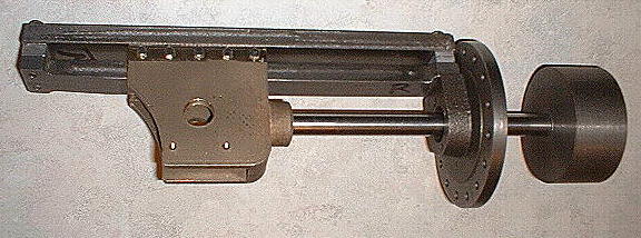
image 48: Rod and Slide Asseembly (removed from loco) The entire piston/rod/slide assembly can be removed. Notice no rings on the piston. That is on the list of things to do later. - 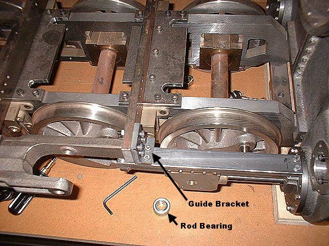
image 49: Crosshead Slide Mounting Bracket 6/4/4 The crosshead guide brackets support the rear end of the slide. It's a critical part because it holds the slide in precise alignment. It takes some time to get it lined up right. Forget about the drawings. This part must be custom fit to the job. I still need to remove a corner from this piece, else the #1 to #2 connecting rod will hit it. Another nice variant to the design is the use of this rod-end bearing. It makes the alignment of the main rod non-critical, and allows the #3 drivers to go over uneven track without binding. Did anyone notice I am building one side of the locomotive at a time? That is because I only have access to one side and it is now too heavy to move by myself. - 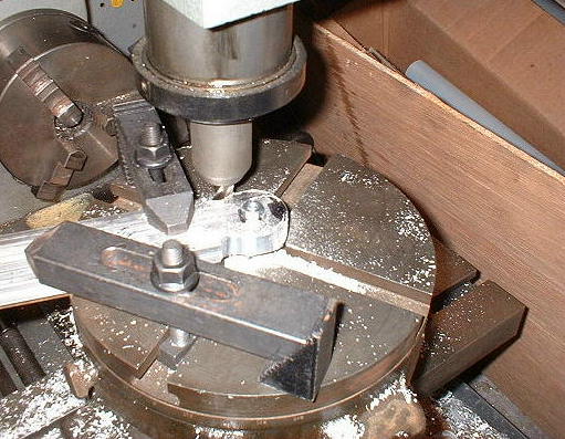
image 50: Milling the Main Rods with the Rotary Table. 6/15/4 I think this is the first time I've ever used Bob's rotary table. It comes in handy when you want to mill the rod ends. These are left and right handed main rods. Ordinarily, they would be fully interchangeable, but I only milled one side of each rod. - 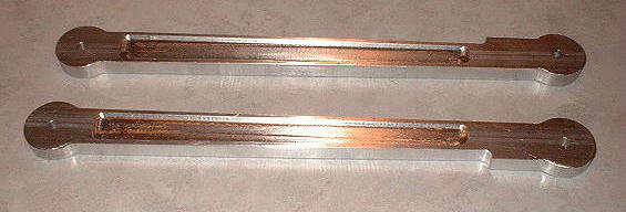
image 51: Main Rods (minus bearings) Completed. 6/29/4 Now that the main rods are done, the next task is to make the connecting rods, starting with the center rod. Critical DimensionsI haven't said much about which dimensions are super critical and which ones are not. The length of the connecting rods really is critical, and must match the distance between drive axles. Otherwise the whole thing just wants to bind up.Another dimension that really matters is the distance between the axle and crankpin centers. The actual dimension isn't too critical, but what matters is that the dimension is the same on ALL drivers. You may hear that "Quartering of drivers must be precise". No argument there, but what really matters is that ALL drive axles are quartered identically, and the actual angle isn't too critical. - 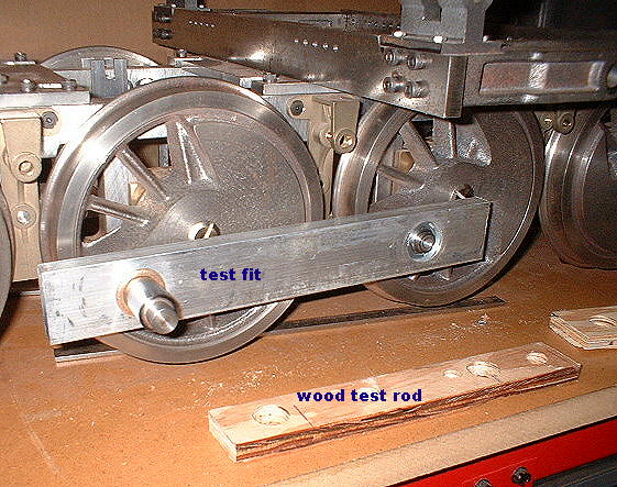
image 52: Test fitting the center connecting rod. Before committing to using costly materials and tools, make a set of test fit rods out of plywood. Once you get these to work smoothly, measure the distance between crankpins to see the actual length required. You can get an accurate measurement by measuring with a caliper, the distance between the insides and outsides of the crank pins, adding the two dimensions, and dividing by two. (a simple average.) If you are within .005" of the drawings, just use the drawing dimension. Otherwise make the final rod according to the actual length measured. Do the critical bores first and test fit them with their bearings and/or bushings installed. If it's close enough, that's great! Continue with the rest of the machining. If not, use the piece for a front or rear connecting rod. - 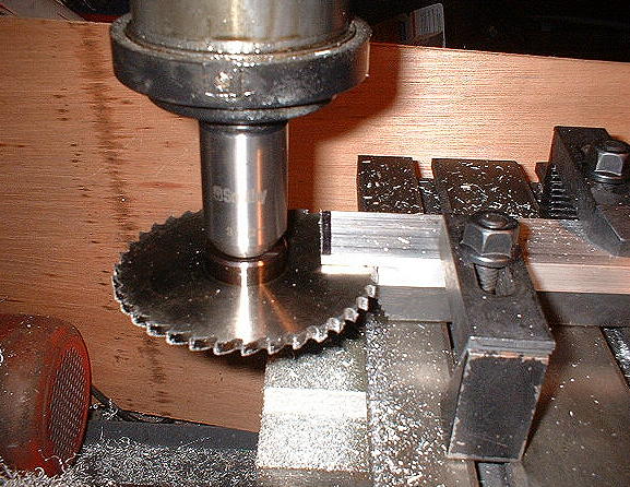
image 53: Slitting the front and rear connecting rods. Speaking of front and rear connecting rods, you will need to slit these to mate with the center rod. This is a very serious tool. Observe all safety precautions. Remove it from the mill when you are done. (On to Page 13) |