Steam Locomotive -- page 13(Back to Page 12) - 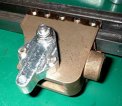
image 54: Drop Link Drop Links serve two purposes. They hold the main driving rod pins in place, and they serve as a pivot for one end of the valve gear union link. It is also an interesting part to make. Drawings assume steel for this, but I use aluminum here. - 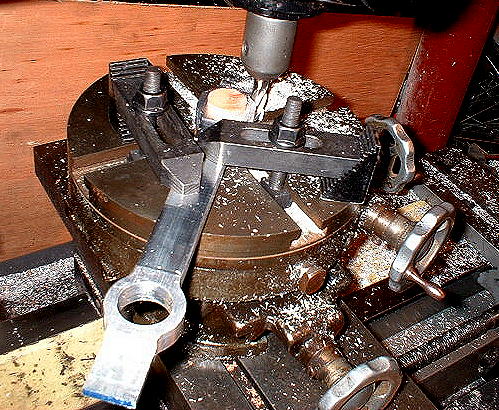
image 55: Milling the Center Side Rods. (notice the wooden centering tool?) Another job for Bob's rotary table is to mill the ends of the center connecting rods. These are the rods in the previous page. Having passed the test fit, the ends, top, bottom, and face have been machined. Despite the drawing, I don't mill the backs. Nobody will see them and they can't collide with anything. Why give up the extra strength? - 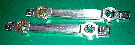
image 56: (almost) completed Center Connecting Rods. All that's left is to drill the front and rear connecting holes, once I decide how I want to do that. Bronze bushings on the #3 (main) crankpins, commercial rod-end bearings on #2 crankpins. 7/15/4 - 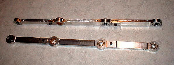
image 57: Completed Connecting Rods. The rod-end bearings are held in place by hollow setscrews. The setscrews are hollow because their bores double as oil holes. Ordinarily using a setscrew to retain a bearing is not an accepted practice. However, the outer race on these bearing is so rigid, there is no apparent penalty for doing it. Should I have these rods black anodized? (On to Page 14) |