Steam Locomotive -- page 14(Back to Page 13) Time to build the pilot truck. The pilot truck is equalized with the #1 driving axle by way of an equalizer beam. The equalizer beam supports the pilot truck, using the equalizer pivot as a fulcrum. On the front end, it puts weight on the pilot yoke. On the back end it connects to a traverse equalizer with the double clevis. The traverse equalizer connects to the front of the #1 axle's leaf springs using the front spring hangers. 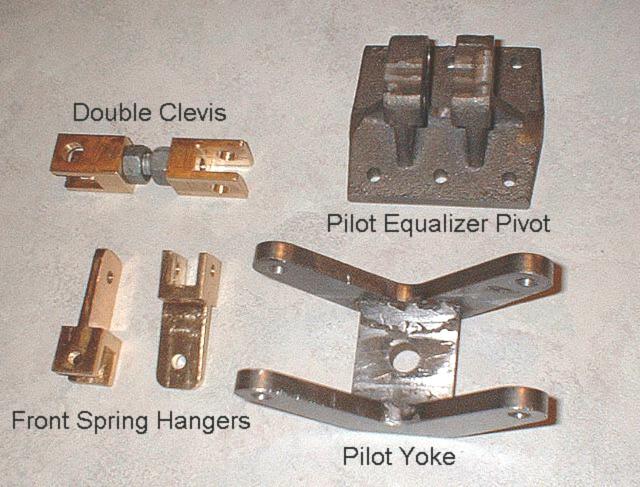 Image 58 - Pilot Equalizer Connecting Parts The drawings call for the double clevis being made out of two parts - a male half and a female half. However, the female half is much easier to make, so I made two of them and connected them with a piece of threaded rod. The drawings also call for rounding of the ends on the clevis and hangers, but that is extra work. The Pilot Yoke is supposed to be silver soldered together. Forget that. Weld it. I filed away part of the weld bead to make sure the head of the yoke pin will clear it. 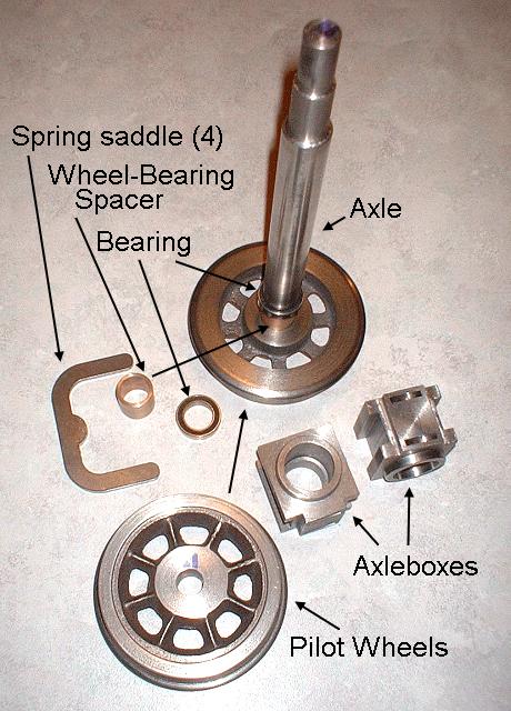
Image 59 - Pilot Truck Parts The axleboxes are fun to make. But the original version of this locomotive used journal bearings, and the current supplier has ball bearing conversion in the drawings. But read the drawings and then toss them out. The bearing should be centered inside the axlebox and it is not in the drawings. Also I took the liberty to make the bearings load from the front. If you do this, there is no way the axleboxes can run out and hit the wheels. They can run in, but the frame prevents them from going anywhere. I also added a wheel-bearing spacer. This keeps the bearing in position in the center of the bearing block. Also, the drawings call for hour-glass shaping of the frame slots in the axleboxes. There is no reason to do this. Make the sides parallel and use the .64" dimension. 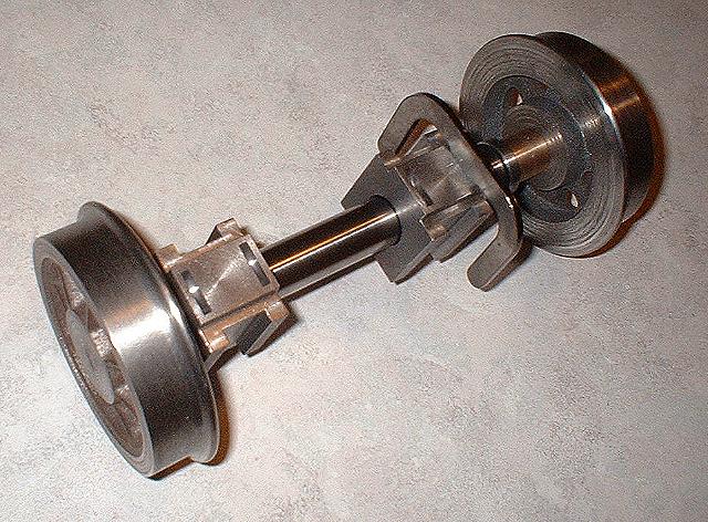
Image 60 - An [almost] assembled Pilot Truck Axle Without frames to hold the axleboxes in position, they are free to be slid inward, revealing the bearing and spacer. Also notice the radial slots in the top of the axleboxes for the spring saddles. These were cut with a Woodruff key slot cutter. 1/12/6 (January 12th, 2006) Pilot Truck Frames, Transom Spreaders, Swing links, Pins, and Radius Bar 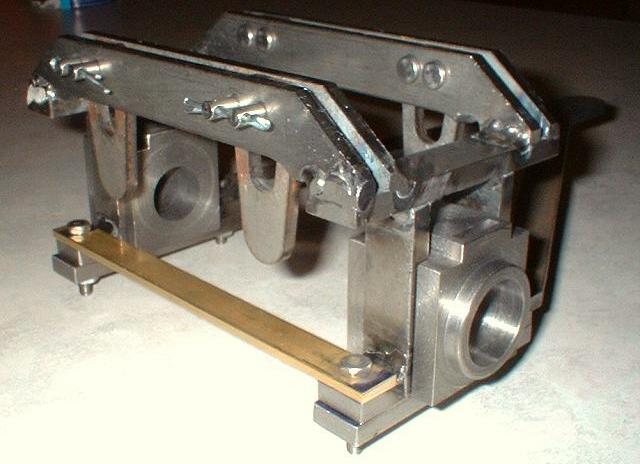
Image 61 - Front view of Pilot Truck This is an all-welded assembly, so it is important to insure that everything is as square as possible and that frame spacing is correct prior to striking an arc. I wonder if the kit supplier knows that you can use one cotter pin for each pair of clevis pins. Also notice that I don't hesitate to use brass or aluminum anywhere. Once painted, nobody will care. Plus, it isn't going to rust. 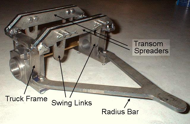
Image 62 - Rear view of Pilot Truck Swing links still need to be drilled at the bottom. The back end of the radius bar also needs to be drilled. To complete the pilot truck, I still need to make upper and lower spring pads, drill the spring saddles, and make the Yoke Swing Pins. The radius bar was a tad too wide to fit, so I had to "Yogi Bear" it a little. 1/13/6 - Swing links, pins, and yoke assembly 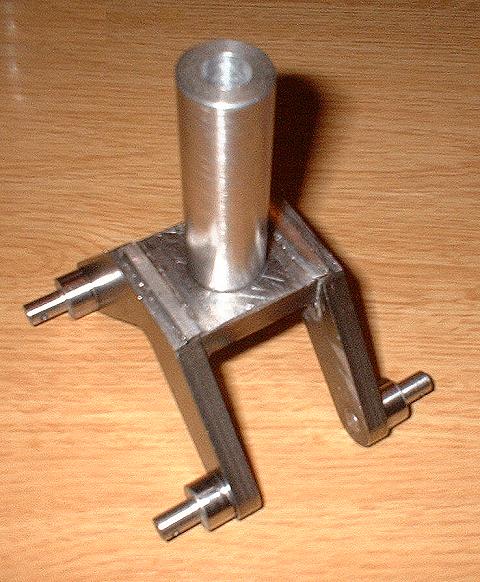
Image 63 - Yoke with main yoke pin and swing pins glued on This is my second try. The first time I tried to unify the swing pins. That was a bad mistake as the extended pins could hit the axle. 1/17/6 -- Putting it All Together 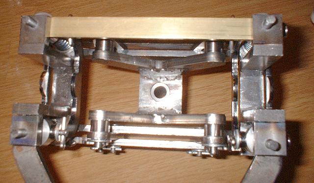
Image 64 -- Springs and saddles attached, underneath view. Now the yoke and swing links are fastened to the overhead transom spreader via 8 clevis pins, which allow the swing links to rock. Spring saddles and springs are also now attached. 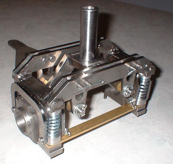
Image 65 -- Springs and saddles attached, front axle removed. This is a good view of how the springs all go together. 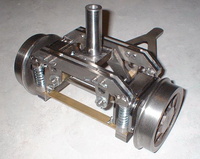
Image 66 -- Completed Pilot Truck. Here it is all ready to go. Except for some self-inflicted rework, that is. This thing has more parts than a Vortek V6 and weighs a ton. It sure works nice, though. Wheels are pinned in place with #10-32 setscrews tapped and driven into both wheel and axle. New saddles were provided by the kit supplier after the originals proved to be too tall. The new saddles really are an improvement over the originals. I still had to file away part of 2 of the transom spreaders. But comparatively speaking, that was no big deal. (On to Page 15) |