Steam Locomotive -- page 15(Back to Page 14) Time to fix some long enduring frame problems. 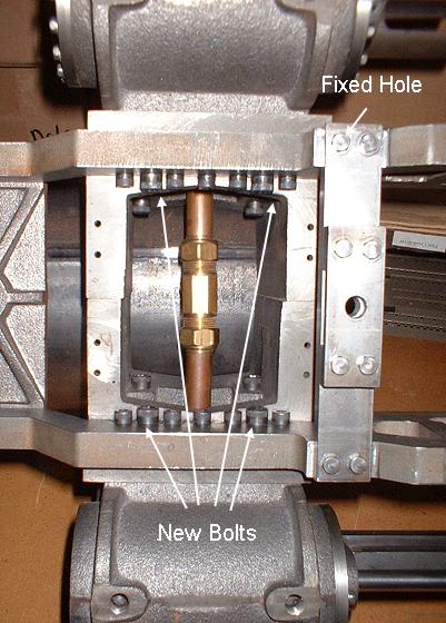
Image 67 -- Replaced Pins with 5/16-24 Bolts. The drawings call for 4 out of the seven holes to be drilled and reamed precisely to 1/4" and steel pins driven in these holes. The reason is to hold the cylinders from moving against the frame under the 400 pounds of constantly reversing force of the pistons. But try as I may, I could not get the pins to fit tight enough to do any good. So in frustration, I drilled out the holes and tapped them for 5/16-24" bolts. I think seven bolts on each side should do it. There was also a mounting hole for the pilot truck radius arm bracket that had a drill bit broken off in it. 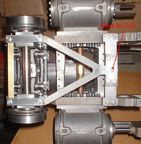
Image 68 -- Time to mark the hole in the Pilot Radius Arm. So I drilled out the broken drill - a long and tedious process - using a carbide drill which continually had to be resharpened until the old bit was completely drilled out. I then oversized the hole (to 5/16") and cemented a 5/16" rod in the hole using loctite 680. I cut the rod flush with the frame, redrilled and tapped the bolt hole, and that was that. Now it's time to mark where to drill the hole in the Pilot Radius Arm. 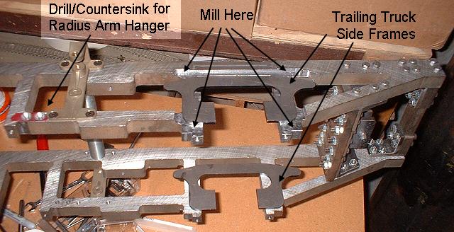
Image 69 -- Frame Modifications for Trailing Truck. Another labor intensive task is to mill the frames down to allow for the trailing truck sideframes to fit between wheel and frame. The drawings call for the entire rear section of the frame to be milled, but that is both time consuming and unnecessary. I just milled around where the frames had to ride. I also drilled and countersunk the trailing truck radius arm bracket mounting holes. The 1915 Baldwin 90 ton 2-8-2 erecting card shows one, but it connects to the trailing truck via some kind of pivot not shown on the kit drawings. Other frame tasks included drilling the rear (#4 to trailing truck) spring oil holes, drill the trailing truck coil spring pad mounting holes, and to fill and redrill equalizer beam mounting holes in the two frame spreaders that were misaligned long ago. 1/31/6 -- January is almost over. Time to build the trailing truck. 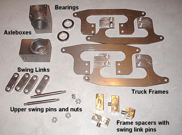
Image 70 -- Trailing Truck Parts. The trailing trucks' axleboxes are much easier to make than those of the pilot truck, although the bearings are a little larger. The system of swing links and pins is also quite a bit simpler as well. 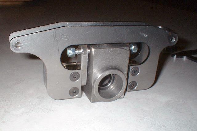
Image 71 -- Trailing Truck Frame partly assembled. As I did for the pilot truck, I also modified the the bearing mounting method for the trailing truck. Again, bearings load from the front and are centered within the truck frame. I could go ahead and mount these on the locomotive frame, but I think I'll wait until I test fit everything with the wheels, axle, and transom spreader in place first. Those will be the next tasks to tackle. 2/2/6 -- January is over. Trailing truck work continues. 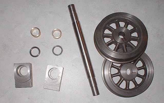
Image 72 -- Trailing Truck Wheels, Axle, Spacers, Bearings, and Axleboxes. There was a little rework needed on the axleboxes. I actually forgot that I am regauging this locomotive from 7.5" gauge to 7.25" gauge. So, as built, the axleboxes would actually contact the backs of the wheels. So I had to remove material from the front of the axleboxes and not bother the tapped holes I drilled for the transom spreader. 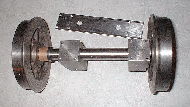
Image 73 -- Axle showing bearing and spacer. Transom Spreader. Just like on the pilot truck, a spacer is used to position each ball bearing on the axle. And here's another new part -- the transom spreader. It's job is to keep the two axleboxes the correct distance apart, and connect to the radius bar. But notice - there are two radius bar holes. That's right. Another modification I am making, uses two radius bars. With this arrangement, I can control the angle of the axle's swing. 2/7/6 -- More tasks to be completed. 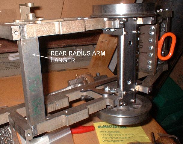
Image 74 -- Trailing Truck mounted + Rear Radius Arm Hanger. Here we see the trailing truck mounted and ready to go. I still need to trim the two pedestal binders for the trailing truck before I can install them. We also see the hanger for the two trailing truck radius arms, cut, drilled, and tapped. But the two holes for the radius arms still need to be drilled. 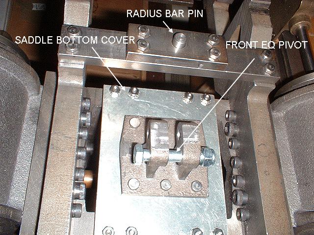
Image 75 -- Saddle Bottom Cover, Front Equalizer Pivot, Radius Bar Pin. The saddle bottom cover is made from 1/4" aluminum. Condensate and garbage from the smokebox can run down through here, so being less corrosive might be a good thing. The equalizer pivot bolts to the bottom of the cover. A 5/16" bolt is the pivot. Also, I made this captive radius bar pin. No nut or cotter pin is needed. It will later be trimmed to length to not interfere with brake rigging. (On to Page 16) |