Steam Locomotive -- page 16(Back to Page 15) Springs and Equalizers 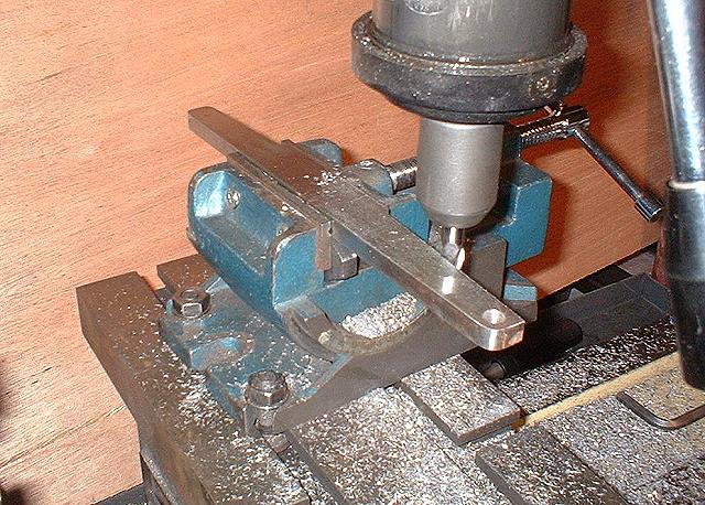
Image 76 -- Milling the Equalizer Beam. Here's another fun part to make. This connects the spring rigging from the drivers to the pilot truck. It's basically a 1" x 3/8" bar of steel. But certain areas need to be milled away to clear the pilot axle and the pilot radius bar pivot hanger. Drawings say, "Check On Job". That's why one hole is drilled. The others will be marked on location with the first hole pinned in place. 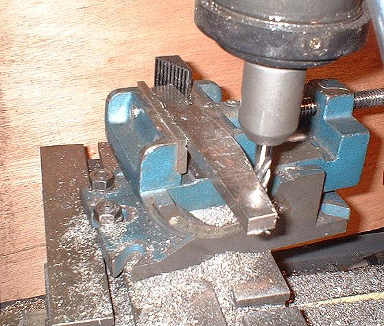
Image 77 -- Milling the Transverse Equalizer. Another fun part, the Transverse Equalizer divides the load from the pilot truck equally to the left and right #1 drive axle leaf springs. You'll see that later. 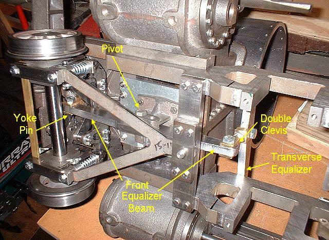
Image 78 -- Lots of new parts installed. The yoke pin connects the pilot yoke to the equalizer bar. It's another nice new part I had to make. The equalizer beam balances on the pivot, which has two choices for the location of the fulcrum. Using the forward pivot puts more weight on the pilot wheels. The double clevis transfers the load from the equalizer beam to the transverse equalizer. Amazingly, all of this stuff actually seems to work.
2/25/6 - Saturday
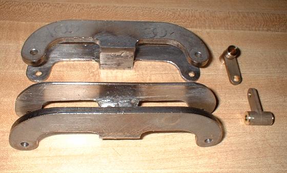
Image 79 -- Equalizer for #4 Driver and Links The number 4 drivers are not sprung the same as the other 3 axles. This is because there is no room for the overhead leaf springs under the boiler and firebox. So this equalizer is used and the spring is inside the frame between #4 and the trailing truck. Another problem in downgauging this locomotive: the equalizer behind the wheel had to be thinned down by 1/8". Another adaptation was to add the bottom push-plate. This has to slide on top of the #4 bearing block. 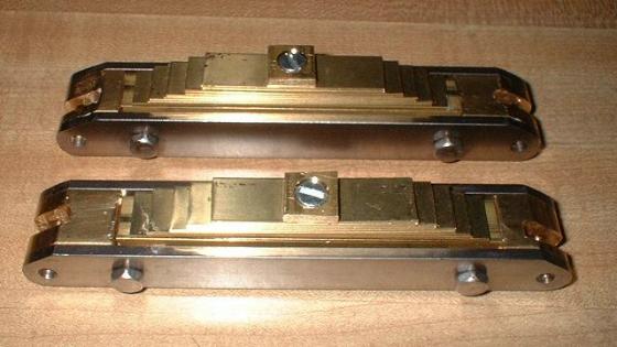
Image 80 -- Rear Equalizer Spring Assemblies Drawings say to silver solder this assembly together. But if it was designed correctly, you wouldn't need to. In the drawings, the ends were one piece and were soldered to the side frames which did not run the entire length of the equalizer. Here, the sideframes run end-to-end eliminating the need to solder. Oh yea. Brass springs? On the other springs, I spent a lot of money on blue steel spring stock, only to find that they didn't flex anyway. I could have used portland cement. So now I use brass. It still doesn't flex. But it's cheap and when painted will look fine. Builder's Note: Some say you should build the locomotive exactly like Baldwin did in 1915. With this kit that is not possible. Everything about it wrong. Placement of the drivers is wrong. Even the track gauge itself is wrong. So if you have to make some variances, why not fix some of the buildability problems at the same time? 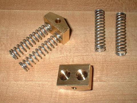
Image 81 -- Trailing Truck Coil Spring Holders And another really fun part to make. The spring rigging and equalizing ends at the back of the frame with these coil springs. I probably won't use these exact springs, but at least they are the right outside diameter. If the locomotive weighs 600 pounds and there are 12 wheels and the weight is distributed equally, each wheel will carry 50 pounds. Each coil carries 1/4th the wheel load, so 12.5 pounds is all they need to support. 3/6/6 - Putting the Spring Rigging together
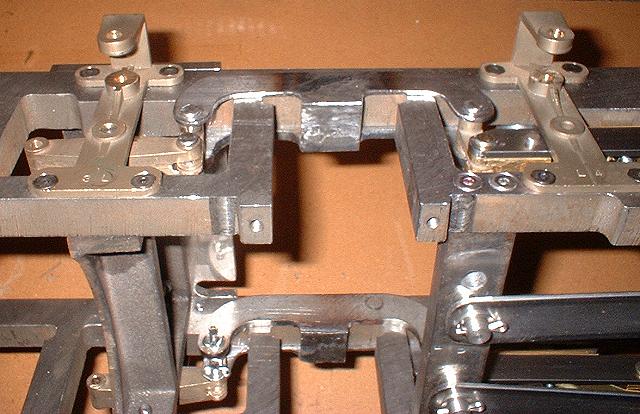
Image 82 -- Number 4 Driver Equalizer Yokes installed Two kinds of pins I hate -- Clevis and Cotter. Clevis pins are never the right length. I end up drilling my own cotter pin holes anyway. And cotter pins are always in a location that you can't get to with a pair of pliers or vise grips so they always come out looking bad. Here the number 4 driver bearing yoke attaches to the rear equalizer and the rocker beam ahead of it. Notice the captive pin holding the rocker. That's an Ed Abate original. 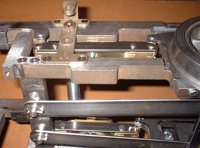
Image 83 -- Rear Equalizer connected to Trailing Truck We are looking at the underside of the rear equalizer spring assembly. Notice the brass clip I added to keep the springs from falling out when you set the locomotive on it's side like I have done. Also notice the dual rear radius arms. That's a me original. (On to Page 17) |