Steam Locomotive -- page 17(Back to Page 16) 3/9/6 - Time for some Brake Work. 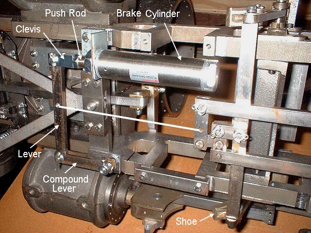
Image 84 -- Brake Cylinder and Levers I decided to mount my brake cylinder inline with the brake rigging instead of at right angles, like the prints show. I also used a compound lever so that the air cylinder would have to deal with only very small side forces. There is a missing link in this photo. It's the pull rod from the brake lever to the brake rigging. I can't really tell how long to make it until all the drivers are put back on. And there are no adjusters anywhere in the brake rigging. Notice the "F" and "1R" stamped on the one pedestal binder. 3/12/6 - Found the missing link 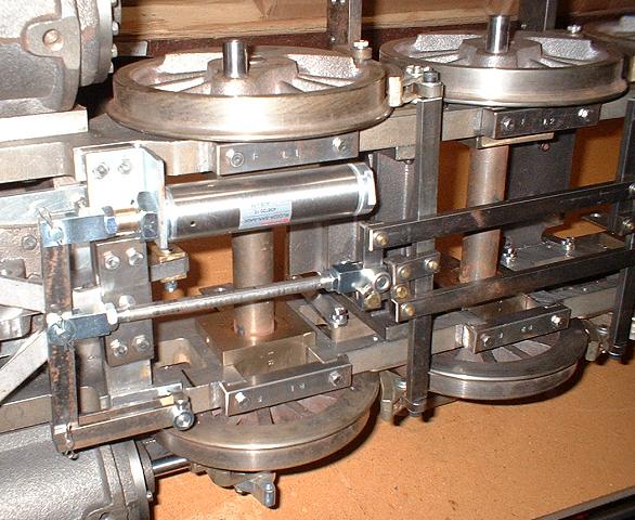
Image 85 -- The Missing Link Installed Like I said, Can't install the missing link until all the wheels are on. Well, wheels are on. But I changed my mind. The new link is somewhat adjustable. I don't know why I bother to machine my own clevises. These nice little chrome plated gems are three dollars each from McMaster. It doesn't make sense for me to make them at that price. 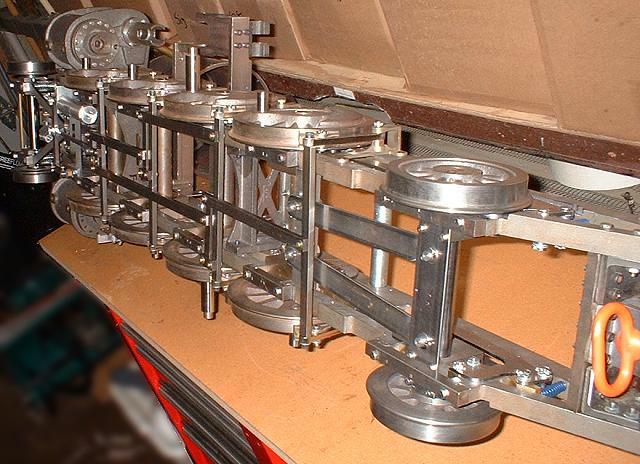
Image 86 -- Lots of Wheels Finally, this is starting to actually look like a Mikado. You know. A 2-8-2. Also, this photo gives a glimpse of what the rear springs and holders actually look like installed. Did anyone notice the HO gauge track in the background? Or the red/green LED signal? These are the remains of my earlier days as a model railroader. 3/15/6 - A low turnover rate 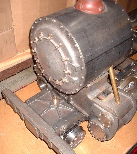
Image 87 -- Finally, Back on it's Wheels For the first time, the locomotive is actually supported by all of it's wheels and not the other way around. Now I need to build a treadmill for the engine, so I can run it in place. 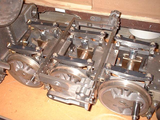
Image 88 -- Leaf Springs Installed. Still need to be leveled and adjusted The leaf springs are all in place. I still need to make spring pads so that all axles are at the right flying height. Unfortunately, with no weight on the back, the rear coil springs are way too strong. Can't change them though. Once the boiler, domes, and cab are on, they will begin to see their rated load. 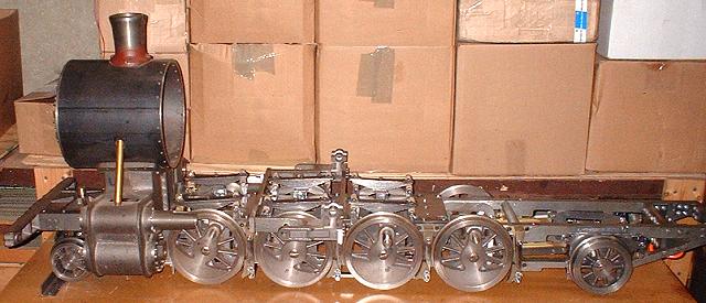
Image 89 -- Time for a Side View Now it's time to stand back and imagine. This sort of looks like one of the demo photos you see in some of the live steam locomotive catalogs. As far as I know, this is a one-of-a-kind. No other supplier sells castings for a light logging Mikado. 3/28/6 - Boiler and Domes I had to take some time off to help the wife paint one of the bathrooms in our house. We will be doing even more fix-up over the next several months. The hobby does not take priority over chores, church, or family. There are two sand domes and one steam dome on this locomotive. One of the more challenging tasks is to shape the bottom of these domes to match the top of the boiler exactly. In the following photo, you will see that these domes have been countoured to match the boiler. Would anyone like to guess how I did this?
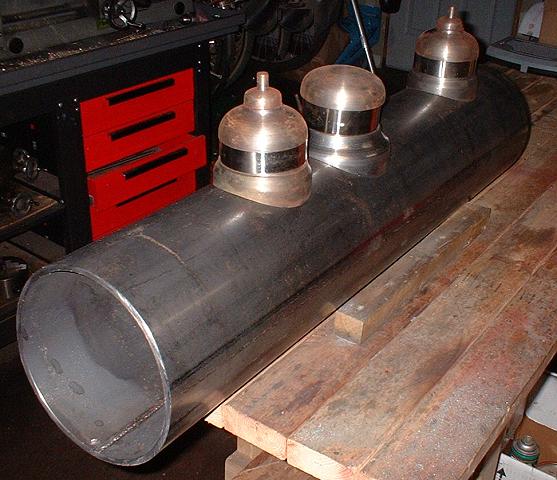
Image 90 -- Domes countoured and boiler cut to length and sloped. Another task is to cut the boiler to the correct length, and at the same time, slope the back of it to match the boiler drawing. So, how did I do that, and what tool did I use? I made a template defining the exact cut-off profile using my computer. The template was then printed on paper, trimmed along the projected cut line, then taped to the boiler pipe at the correct location. The cut line was transfered to the pipe by spraying red primer along the cut line of the template. The paper was removed and a hacksaw was used to cut the pipe along the cut line. Could you tell this was done with a hacksaw? Believe it.
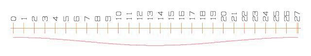
Image 91 -- Cutoff template for the boiler rear slope. 4/8/6 - April already? Time to cut into that boiler. Now I need to cut away the bottom half of the boiler for about a foot for the firebox. You know. The place where you build the fire. Having better tools would really help here. But I don't have them. Once again, I resort to the hacksaw to do the cuts. Remember, it's all I have that is capable of the job. 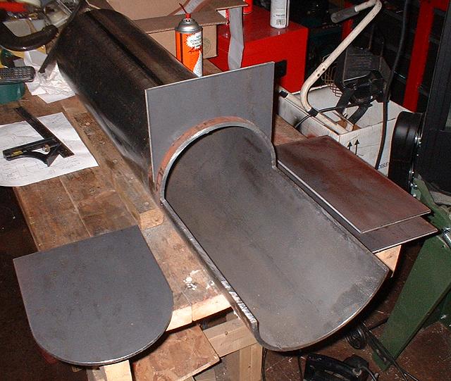
Image 92 -- Cutout in Boiler for Firebox + Firebox walls Yes, that is AeroKroil. It makes many jobs easier. But it gets worse. The hacksaw is only 12" long and the longitudinal cuts are also 12". That means for the last 3 or 4 inches you can't use the hacksaw. So what did I use? Just the hacksaw blade. It's work, but it's all I've got. I also made the curved boiler backhead and firebox front wall cuts in unison using the bandsaw. This was comparatively easy. In the photo, you will also see the firebox sides. These are already the correct height, thanks to Online Metals. I only need to cut their back slope and take a bite out of the lower front corner for the sloped front wall. 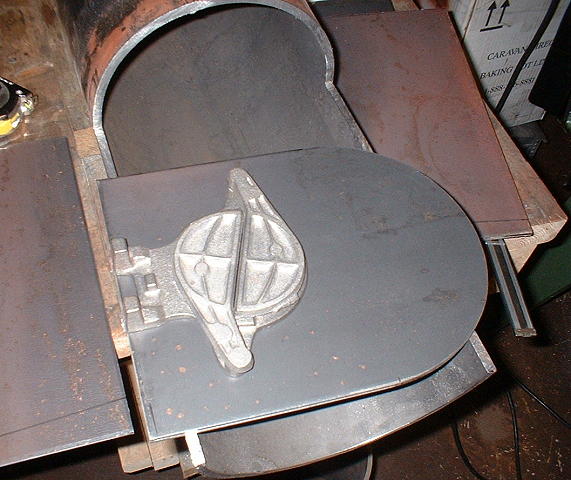
Image 93 -- Fire Door on Boiler Backhead. Eventually I will need to cut some holes in the boiler's rear wall for steam and water lines, control rods (throttle and whistle), and of coarse, the 3 inch hole for the fire door. Here, I've set the fire door castings on the back wall. (On to Page 18) |