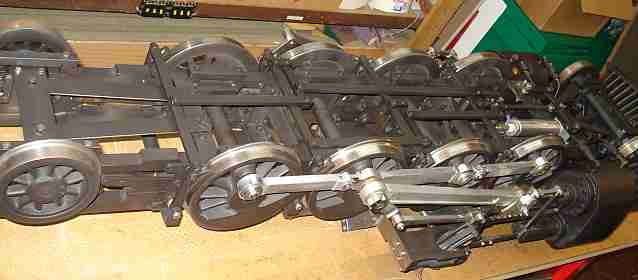
90 Ton Mikado, Page 31(Back to Page 30) I bought five of the Grover-Trophy American Slide Whistles to use to make my steam whistle. I plan to use only 4 of them, slide them to the desired notes, cut off the rest of the slide handle, and mount them in a fake air tank under the rightside walkway. 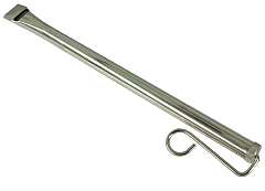
Image 195 -- Slide Whistle But one problem of using a whistle designed to be played by a musician is, one must come up with a way to operate the whistle, or in this case, four whistles on steam or air. 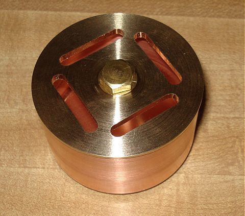
Image 196 -- Whistle Manifold So I made this little 4-whistle manifold out of a 2" copper pipe cap and some brass sheet stock. The center bolt is only used as a means for chucking the workpiece in the lathe. The four slots were designed to accomodate the mouth-piece of the four whistles.
1/14/10
Image 197 -- Whistles Soldered into Manifold Plate The individual slide whistles have been soldered onto the manifold plate. I have also drilled the inlet hole into the manifold cup and soldered the manifold plate and cup together. Next thing to do is to build the air amplifier or venturi. The whistle must use an air amplifier to converts high pressure, low volume steam (or air) to low pressure, high volume air. This is necessary because these whistle require a lot of air, but thankfully at very little pressure. Mixing in of outside air has other advantages. When running with steam, the whistle will sound better, because it will condense out most of the water. It also reduces the temperature of the air entering the whistle.
Daily Progress Notes
4/1/10 - Painting the UndersideApril 15th is coming up. Time to do a rollover and paint the underside of the chassis. 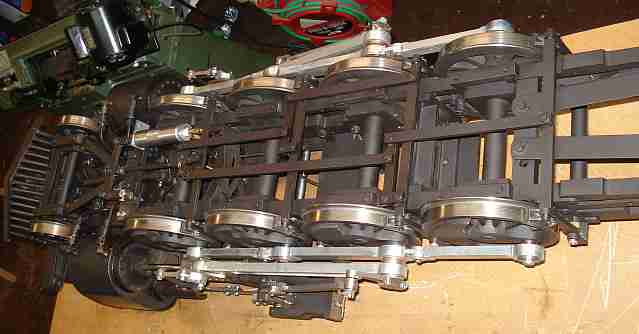
Image 198 -- Underside painting - (right side) As I said earlier - I really like this paint. It's Rustoleum's high temperature barbeque grill paint - good to 1000 degrees F. It's black but not quite. It has a bronzish cast in bright light. But this can has gotten old and is no longer satin finish and has turned to a flat finish - just fine for the underside. They don't recommend priming. That suits me just fine. But it does not stick to oil worth a darn. So clean up as much as possible before painting. That saves some rework. I suppose some builders prefer to paint the individual parts first as the locomotive is being assembled. Others might completely build the engine (as I have) and then completely disassemble it to paint it. That's a lot of work. - Not me. Finish the locomotive first and then paint it. The superstructure is already painted, so all I am dealing with is the chassis. Spray everything you can. Then wipe the paint off the tires and the side rods and anything else you dont want painted. And don't get paint in the drain holes of the cylinder cocks. I did remove the brake rigging, trailer arms, piping, and the pilot truck to get better access to the frame and to paint these items separately. But it took minimal time to do that. This paint does not have a tendancy to run, even if oversprayed multiple times. This is great because when spraying through the wheel spokes to paint the side of the frame you find some surfaces getting hit with a lot of paint. I don't think I have a single run anywhere.
4/8/10 - Painting the Frame Topside
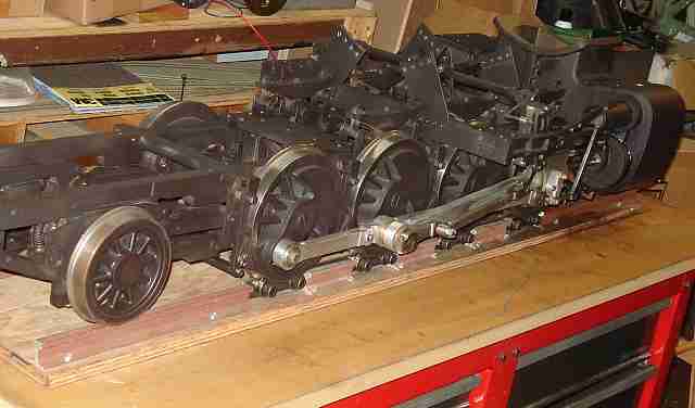
Image 200 -- Chassis Topside Painting So I did another rollover and painted the top side of the chassis. Actually there was very little to paint. Painting from underneath got most of everything covered. I did move the boiler weld on tabs (which are not welded to the boiler yet) so that they were all on the same side of the angled supports. This will make it easier to lift the boiler once welded. So now I'm ready to bolt on the boiler, weld the tabs, hook up the piping and set it on the track.
4/19/10 - Cutting and Securing under-boiler piping
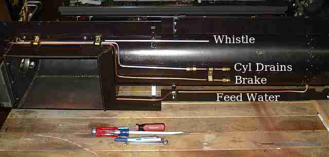
Image 201 -- Piping under the Boiler One of those loose-ends items I needed to address was cutting the brake pipe and cylinder drain pipe to proper length to line up with the fittings on the chassis and install the couplings. It turns out - the cylinder drain valve pipe was too short, so I had to add a piece of pipe and use two connectors. I also wanted to secure the ends of the two pipes while I was under there, so I made a little brass clamp and used teflon tubing as an insulator. On to Page 32 (Back to Page 30) |