90 Ton Mikado, Page 30(Back to Page 29)
12/2/9 - Misc ItemsSeveral items were tackled in recent weeks. I did include photos of some of these items. Most are small and have been put off for some time.
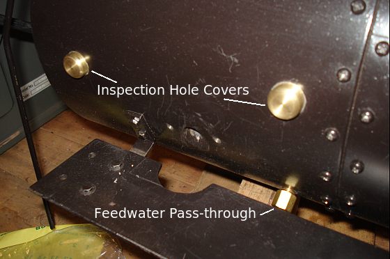
Image 185 -- Inspection Knobs and Feedwater Pass-through There are 2 smokebox inspection hole covers on the left side and one on the right side of the locomotive. These are just large enough to get a flashlight through and be able to peek in looking for boiler tube leaks, etc. The feedwater pass-through is just a 3/16" OD compression union that has been tapered and pressed into a hole in the left side of the smokebox.
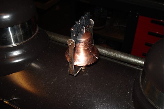
Image 186 -- The Liberty Bell I wanted a bell that was larger than the tinkly brass bell I bought from Cannonball and was different from what everyone else had. My son picked up one of these liberty bells when he was visiting Philadelphia. But he wouldn't let me have his. So I had to make a special trip to Philly and go get my own. OK. So I was already at the airport on a business trip. I still had to get one.
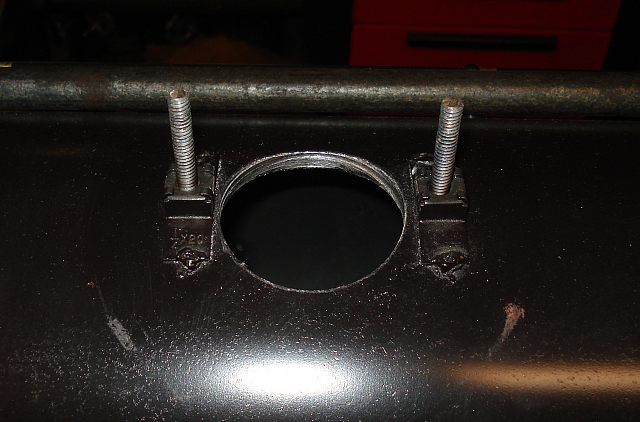
Image 187 -- Steam Dome Boiler Hole Need access to the top of the boiler to hook up the water glass? Just cut a 2+1/4" hole in the outer shell under the steam dome and we are all set.
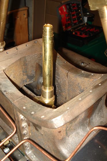
Image 188 -- Threaded Stack Pipe Adapter One annoying problem was with my exhaust pipe. It used a piece of 1/2" copper pipe, joined to the exhaust tee with a compression fitting. The only problem was - once the smokebox was in place, I couldn't get at the nut on the compression fitting to tighten the connection. The solution: Make a threaded adapter for a 1/4" NPT nipple. It's about the same size as the 1/2" copper. But now I can thread the new pipe in and tighten it after the smokebox is in place.
12/29/9 - ThrottleToday I built the throttle handle assembly, consisting of...
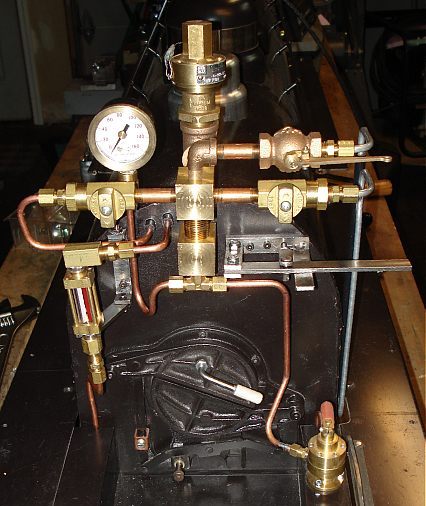
Image 189 -- Cab Piping I made two 1" brass manifolds to connect the aft end of the live steam pipe from the boiler to the cabside appliances. The lower manifold is a 3-way cube that connects to...
Both pipes to the water glass are dummies. They go inside the boiler shell and end. Without a real boiler, there is no water level to monitor. The blower tube is also a dummy. It ends inside the boiler shell. That will however eventually connect to the exhaust stack. Also notice the throttle handle in this photo. I still have some shaping to do on the handle, etc. But I can do that later.
Making a Cheap Gauge Look PrototypicalAntiqueing a cheap gauge can be as simple as adding a bronze ring to the face of it. The gauge in the above photo cost $7. I made a brass ring out of bearing bronze which fits in front of and around the instrument. I have it glued in place with RTV silicone.
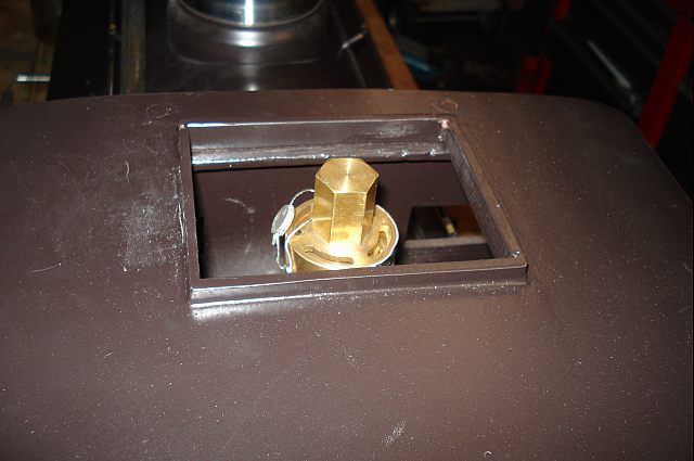
Image 190 -- Safety Valve in Cab Roof The cab roof already comes with this large rectangular hole. I was trying to decide what to do with it, and - at the same time - try to find a place for this huge safety valve that the state of New Hampshire requires. Applying a little logic, I decided to let the two problems solve each other.
1/2/10 - More Detail Work - (2009 already gone. - ugh.)Here's some more items that were tackled in the past week.
The "Ersatz" boiler is simply a piece of 3/8" NPT pipe that replaces the real boiler until the real boiler is ready to install. In the mean time, it allows me to operate the locomotive on compressed air. it is suspended from the top of the boiler shell with two bolts under the #1 sand dome. Even though I plan to initially operate the locomotive on air, you may notice I am still building and installing appliances that are not required for air operation, such as feedwater line, waterglass, etc. This is because I want to be able to eventually operate both on air and on a real boiler. I had to replace the tee between the throttle valve and the branch pipes because the original was too wide to fit inside the smokebox at the height required by the Ersatz boiler. Additionally, I had trouble with the heads of the smokestack mounting bolts interfering with the branch tube adapters. This took two revisions. Initially I made a Tee using a piece of 1" brass square bar. Still had proximity issues. Second attempt, I made a "Y" out of the same stock. This made the brances closer together and allowed the use of 1.5" long pipe nipples to avoid the stack screws.
Daily Progress Notes
With the water glass mounting wings the same length, the glass would sit at the same angle as the boiler backhead. But I really want the glass to be as level as I can get it. Making the upper wing longer by about 1/8" compensates for the backhead slope. 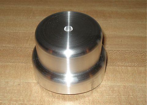
Image 191 -- The "Extra" Dome The "extra dome" appears on the Baldwin erecting card, but is not included in the box of rough castings or any of the supplier's drawings. I assume it houses the prototype locomotive's safety valves. I've had a 3" diameter chunk of aluminum laying around for 39 years that finally got used for this. 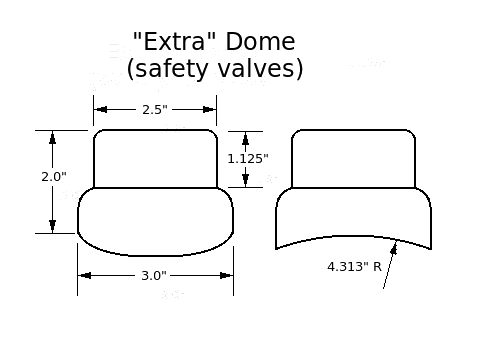
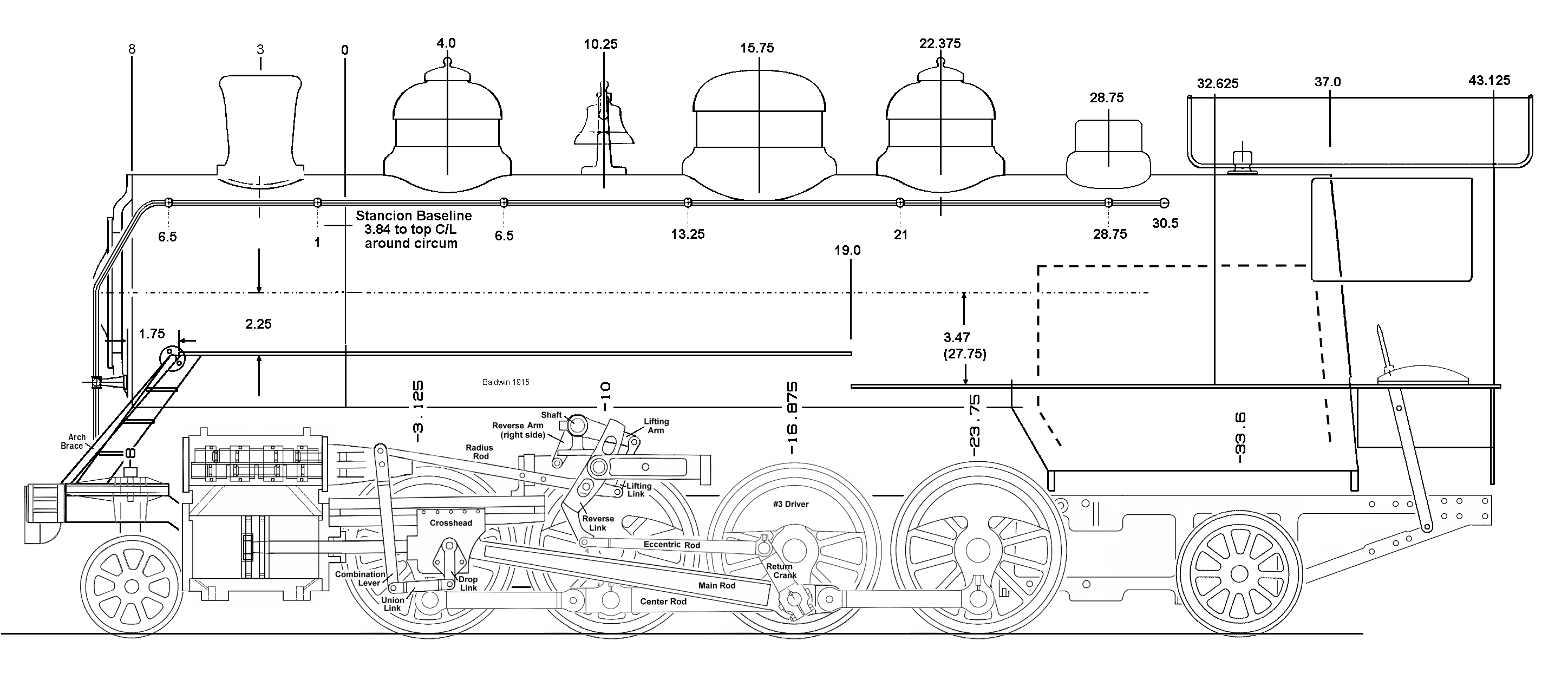
Image 192 -- The "Extra" Dome drawing Here's a mechanical drawing in case you want to make your own. Use this link to view the Mikado leftside drawing which shows the dome just in front of the cab.
Daily Progress Notes
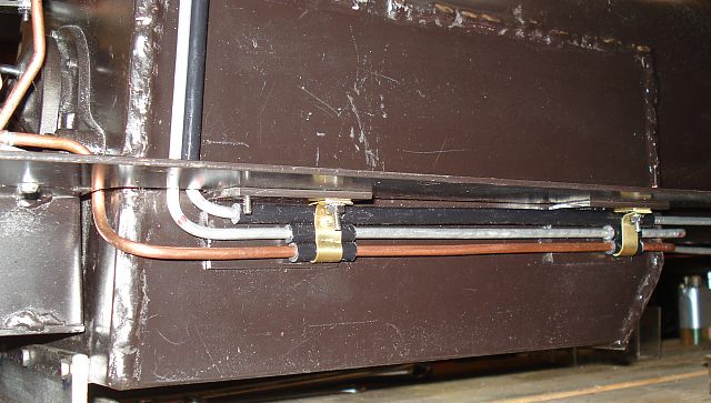
Image 194 -- Piping secured under right walkway I also secured the right side pipes beneath the right side walkway. I can paint all of these later. Notice the whistle pipe running inside a teflon tube. Top to bottom: Whistle, Cylinder Drain, Independant Brake.
Daily Progress Notes
On to Page 31 |