90 Ton Mikado, Page 29(Back to Page 28)
9/21/8 - Semi-Automatic Cylinder Drain ValvesThese are "Semi-Automatic" meaning that water can freely run out when there is no steam pressure to close them. Steam pressure closes the ball valve against it's seat. But the valve can also be forced open by applying steam pressure to the back end fitting. 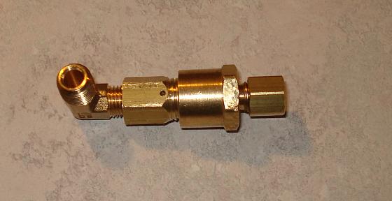
Image 178 -- A Semi-Automatic Cylinder Drain Valve The front end contains a ball and seat. The back end contains a cylinder and a piston with a needle that can force the ball off it's seat, thereby re-opening the ball valve. 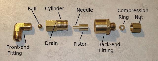
Image 179 -- Exploded View - Cylinder Drain Valve 
Image 180 -- Exploded View - Cylinder Drain Valve After operating Russ Page's 2.5" scale 7.25" narrow gauge steam locomotive, I decided to make it possible to manually open the cylinder drains. It adds to the realism of operating a steam locomotive. 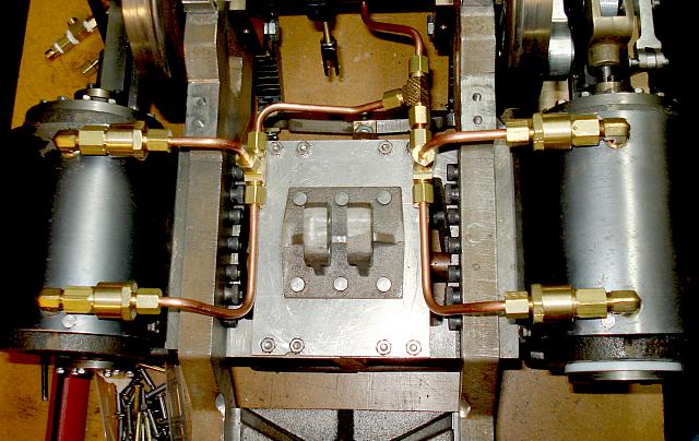
Image 181 -- Piping the Cylinder Drains The valves are all piped together and will be operated by a valve in the cab.
8/3/9 - Moving the Reverse ShaftThis chassis always ran well in forward, but always ran poorly in reverse. The problem was - in the reverse position, the pivot point on the lifting arm was too far from the reverse link pivot point. When the reverse link would roll forward, the radius rod would pull against the lifting link, causing the radius rod to lift and potentially hit the top of the reverse link. This in turn caused poor valve timing in reverse.
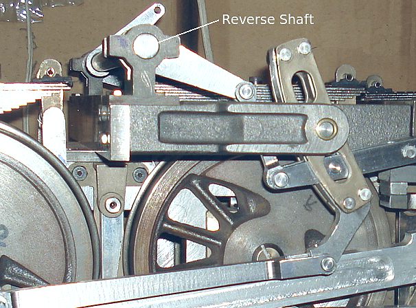
Image 182 -- The OLD Reverse Shaft location Raising the reverse shaft and moving it forward would help, but the lifting arm would collide with the reverse link long before one could move it far enough forward to fix the problem. The solution -- Move the reverse shaft ahead of the reverse link. This way, the lifting link is on the same side of both pivot points. 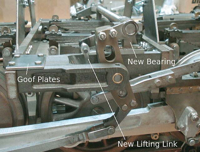
Image 183 -- The NEW Reverse Shaft location This permits the lifting arm pivot point to be moved forward without having to worry about it or the lifting link hitting the reverse link. Now the chassis runs equally well in forward and reverse. I did have to make new reverse shaft bearings as the lifting arms now must run outside the bearings. I also had to make longer lifting links since the lifting arm can't reach down into the link bracket as it could before. The reverse shaft had to be shortened by about four inches. It is no longer the widest part on the locomotive. I had to make two "goof plates" (one for each side). These cover up the old reverse shaft bearing locations on top of the reverse link brackets and populate the old screw holes. Here's a video clip of the chassis running on air after moving the reverse shaft...
Note: I did not invent anything. Many locomotives use this reverse shaft location. It took Baldwin a few years to figure this one out.
11/13/9 - Mechanical LubricatorA Mechanical Lubricator is a device used in Steam Engines to force lubricating oil into the cylinder(s) against the prevailing steam pressure. This has been a major stumbling block for a very long time. I started by trying to use a mechanical lubricator from one of the live steam suppliers. First, the unit seized up and I had to disassemble it (although I couldn't find anything wrong with it). Then I noticed one of the internal check valves wasn't working. Branch pipe pressure was forcing air (or steam) back through the lubricator. Next I noticed it didn't deliver under pressure or at low speed. It was difficult to come up with a scheme that would deliver tiny quantities of oil consistantly with up to 125 PSI of pressure at any train speed. I've spent almost two years and tried about 7 different designs. But most of the designs I tried had the same basic set of flaws. In all, the pressure and quantity of oil they delivered was related to train speed. This is a serious problem since the higher steam pressures are generally seen at the lower speeds. You get the least oil when you need it the most. Some suggested using a "Displacement Lubricator". These are simple and work very well when operating on steam. They don't work at all when operating on air. I need to be able to do both. 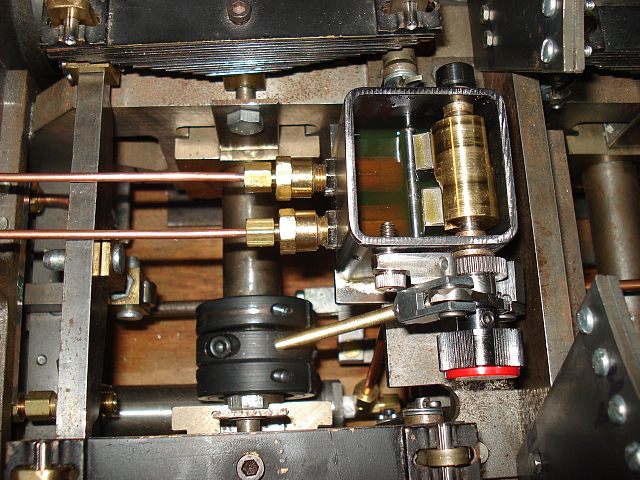
Image 184 -- Finally, A Mechanical Lubricator that Works The lubricator shown here is quite different from more traditional designs. Sure it uses pistons and cylinders like any other. But other designs use a cam to apply pressure to the pistons and return springs to pull the piston back out of the cylinders. This design uses springs to apply pressure to the pistons and a lever and cam to pull the pistons back. But the cam releases the pistons instantly, making the delivery pressure independent of axle speed. Here's a short video of the Luber in operation...
|