|
_
90 Ton Mikado, Page 35
Latest Updates...
January 10th, 2019
Rust Rust Rust
One of the (many) down sides of living in New Hampshire is the fact that everything
rusts. One cannot keep a motor vehicle more than 12 years since the frame will simply
rust in half.
What causes the rust is quite simply the use of road salt in the winter. One would
think it would be confined to the roads, but in reality it comes into contact with
everything. I had a lawmower stored under the deck rust out. My F7's main alternator
had salt stains on it's aluminum casing. Most of the steel sides under the battens
rusted and the battens fell off. And yes, the Mikado was a real ruster.
Most of this last upgrade was about removing rust and repainting, which required lots
of disassembly.
Regauging the Locomotive
7.25" to 7.5"
The first and most troublesome change (and I won't call it an improvement) was
regauging the Mikado from 7.25" to 7.5". This was neccesitated by moving from
New England to the mid-south.
-
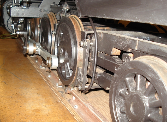
Image 225 - Left side after regauging
Regauging the wheels was easy. Since the drivers were bolted on (just like on
an HO scale model) all that was required was putting a 1/8th inch thick washer under
each wheel and bolting it back on.
The pilot and trailing wheels were a little harder
since they are pinned on with set screws tapped and driven into the axles.
-
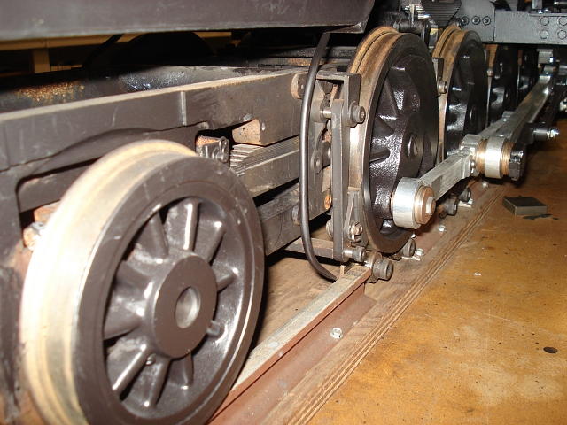 Image 226 - Right side after regauging
The biggest problem was the brakes. They too had to be regauged. They were designed
to shuttle left and right with the axles, but did not expect or allow the shoes to
move outward in opposite directions. Longer shoulder bolts were ordered to allow the
brake arms and shoes to run at the extra width.
Some modification of the side rods was required as clearances under the crosshead
changed. I even had to shorten the #1 crank pins by an eighth of an inch.
The eccentric rods had to be regauged as well since the return cranks stick out
farther than before and the rods didn't align with the reverse levers. That one was
easy. Just turn the link-crank bearing over so that the thick side is on the
outside. This engine really was designed to be regauged.
But worst of all, before I could do anything, I had to change my treadmill to the
new gauge. This required rolling the locomotive off, repositioning the bearing angles,
and then rolling the engine back onto a fixture that it no longer fit.
Cab Lighting - Bolt LEDs
I got tired of the old bayonet style incandescent lamp lighting my cab.
It was just not bright enough. So I bought these License Plate Bolt LED
illuminators.
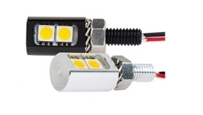 Image 227 - Bolt LEDs (silver or black)
I bought the black ones. Don't need any shiny metal inside the cab. I also made a little
folded aluminum mounting box to hold the lamps and cover the wires. Also (not visible) I put the lamp wire in a 3/16" copper tube painted black to simulate electrical conduit.
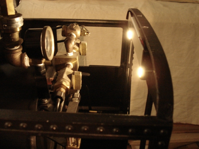
Image 228 - LED lamps on the cab back wall
These are much brighter than the old lamp. You have a choice of cool white or warm white. The warm white is close to the old incandescent color. They also come in Red, Amber, Green, Blue, and UV, so you can use them for other things - like caboose markers.
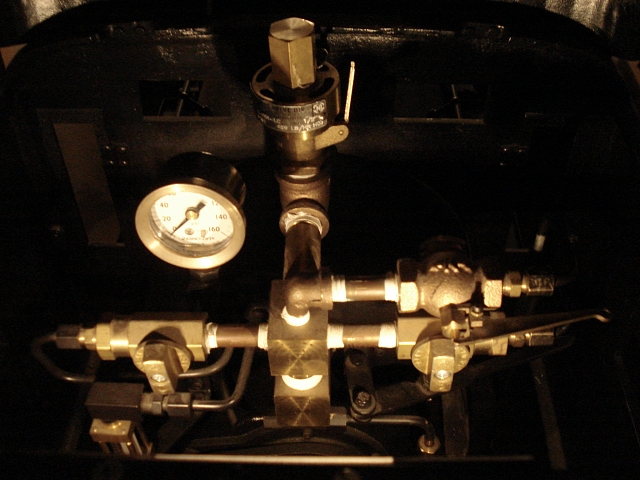
Image 229 - Gauge and Water Glass Visibility
Now it's easy to see the pressure gauge, the water glass, and all of the valves
in the total dark.
Changes to oiler cams and lever
The mechanical lubricator has worked well since day one. However, being from New
Hampshire, much of it had rusted. So it was removed, and rusted parts - like the
main lever - were replaced with brass parts.
But if I had a complaint about it, that would be the cams were too abrupt. The cam
shaft makes a full rotation to reset and fire each piston, so the cams could have been
a lot more gradual. Ideally, the piston return would utilize the entire rotation.
I don't have the means for creating a true involute cam in my lathe, so I did the best
I could by repositioning it in the four-jaw lathe chuck and creating a progressive
ramp. Not ideal, but better than what I had.
Terminal Block and Connector
The electrical wiring on the Mikado was always an afterthought. Wires were twisted
and attached to various objects with nylon wire ties and Gorilla Tape. It was neither
aesthetic or servicable. In fact during the filming of one of the runs it developed
a short somewhere and I had to abandon most of it just to make the headlight work
for the video clip I was creating.
Some of the wires ran up the center of the boiler. That would have to be redone if I
ever got a working boiler.
-
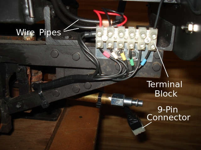 Image 230 - New Terminal Block under the cab
So in this last overhaul, all of the wiring was removed and scrapped.
The cab switches were removed and would later be implemented in the tender.
This necessitated a multi-pin connector. I also added a terminal block to join the
connector wires to their destinations.
-
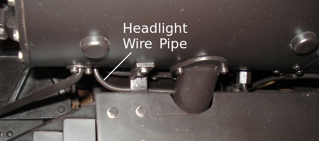 Image 231 - Headlight Wire Pipe entering the smokebox
All wiring to the headlight, bell, and cab, are now in 3/16" copper tubing to look
like electrical conduit.
-
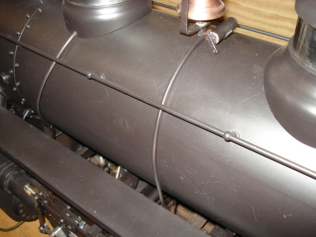 Image 232 - Bell Motor Wire Pipe
New Reverser Tensioner
The Johnson Bar (reverse lever) is locked into the selected detent with a spring.
But the old design was more complicated than it needed to be. So I simplified the
mechanism with this simple one-spring design.
-
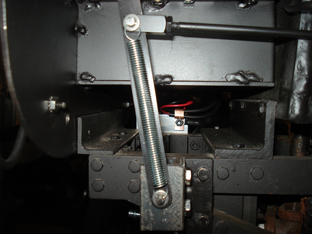 Image 233 - Modified Reverse Lever Tensioner (spring)
Binding Up
After getting it all back together it didn't seem to run the same as before. When the
left side reached top-dead-center the wheels became harder to turn. This could only
be caused by the regauging (or maybe regauging the treadmill).
Removing siderod bearings one wheel at a time revealed the problem
was limited to the left side. In the critical position, the left connecting rod was
stretched pretty tight.
Even though all crank pin holes were drilled in the wheels using the same template,
the pin to axle distance varied from wheel to wheel - not by much, but enough
to cause the binding. This was most likely caused by using Loctite 680 to secure
the pins. That adhesive requires a minimum gap which, if provided also gives
opportunity for error.
The biggest error was found to be axle #3 having the least pin distance. As the
bearings are very precise, there was no room to accommodate the error on the one
end of it's travel. The opposite end was fine and top and bottom positions
just don't matter.
The chosen solution was to remove about .005" from the front end of the #3 bearing
hole, giving clearance only where needed. Not a perfect solution, but overall probably
the best.
-
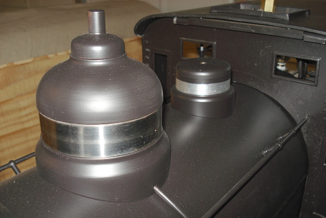 Image 234 - Extra Dome (the small one) Painted like the others
The "extra" dome used to be just a solid aluminum color. When it was new it looked pretty
like that. But now that it is tarnished like any other chunk of aircraft aluminum,
it was time to paint it like the other domes.
(Back to Page 34)
Or use your browser's "back" button.
|