90 Ton Mikado, Page 34(Back to Page 33)
3/21/13 - Trailing Truck ModificationAfter testing on the main track one issue that came up is just staying on the track. It turns out, even with extra travel built in to the bearing blocks, my 38 foot radius curves were still too sharp. Going forward wasn't so bad, but backing up, the trailing wheels wanted to climb over the rails. 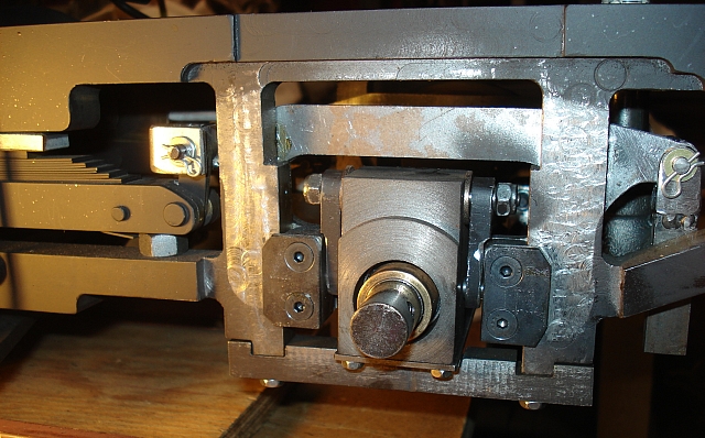 Image 217 -- Changes to Trailing Truck Frame. So I modified the trailing truck frame to give the wheels more swing. I moved the outer truck frames to inside the locomotive frame. I also took about 30 mils off the back of the wheels. This gives about .3 inches of total extra travel. You can see the new "frame grabbers" that were added to replace the outer truck frame. These run inside the back of the wheels which had to be machined to clear them. The rear link and frame still need to be drilled and pinned once the correct running height is determined. The nut you see under the leaf spring is holding up the locomotive while the trailing wheels are off the ground (or missing).
7/17/13 - Pilot ModificationsOne issue I had when testing the locomotive was simply getting on and off of the lift. The pilot would strike either the lift extension or the loading track. I would have to continually change the lift height to get the loco to move. Finally the height of frustration was reached when the pilot broke off, leaving pieces of boiler tube on the ground. Additionally, I had problems with the coupler height. The coupler centerline was almost an inch too low and the pilot mounting didn't look right. It was originally fastened to the bottom of the pilot beam with a pair of angle brackets. The bottom of the pilot beam was not square with the front causing the pilot to point downward. 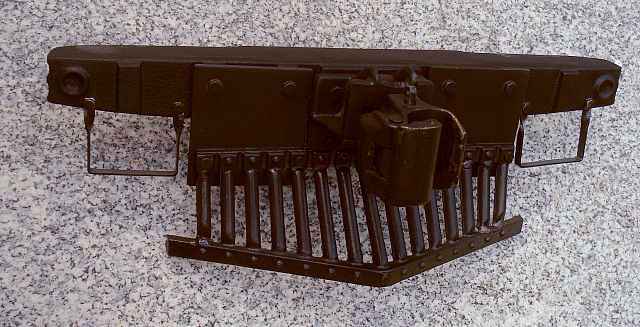 Image 218 -- Changes to Pilot Mounting To correct the coupler height problem I simply inverted the coupler pocket. This made the height much closer. But I had to cut off a shelf that was part of the coupler pocket. Now being on top, it interfered with the coupler pin. While at it, I also cut about 1/4 inch off of the bottom (previously top) of the coupler pocket's mounting plate. This allowed me to mount the pilot higher by this amount. Next I repaired the pilot by welding all the broken pieces back together. I then mounted it to the front of the pilot beam using a pair of 1/8" thick steel plates. This corrected the angle issue and part of the clearance problem.
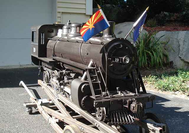 Image 219 -- Pilot Beam Reinstalled And while I have the pilot beam off of the locomotive, might as well add those steps and paint everything. I had seen these steps in a number of prototype photographs. Thanks to Precision Steel Car Company for providing them.
7/22/13 - Compliance TestingCompliance Testing
8/2/13 - Drain Valve ModificationThe semi-automatic cylinder drain valves (described here) work just fine. They only have one problem. The drain holes are positioned directly over the railheads. This of course means water and cylinder oil get dropped directly onto the rails. Why is this a bad idea? 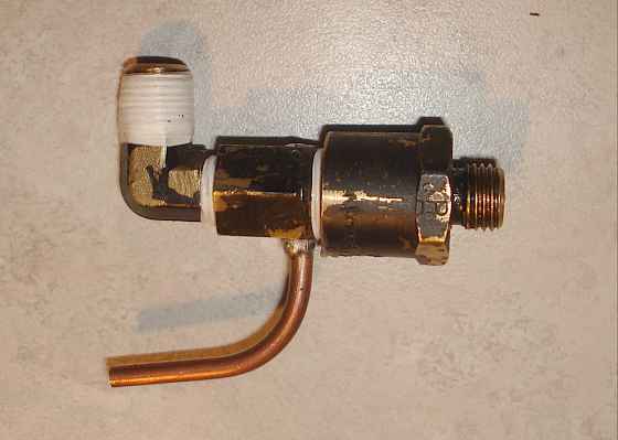 - Image 220 -- Modified cylinder drain valve To prevent this I had to remove all of the drain valves and add this copper drain tube to each one. It's a simple fix, but an important one. I also had to retest each valve and found that two of them needed to be lapped.
10/24/13 - Piston Valve ModificationI never liked the fact that the locomotive always had to work against it's own compression because for most of a stroke the exhaust ports are closed. In a single valve rod system, when valve timing has been optimized for the steam inlet stroke, timing is less than ideal for the exhaust stroke.
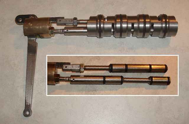 - Image 221 -- New Valve Liners and Valve Rods
So I came up with this 2-valve configuration. Now the inlet and the exhaust each have separate valves. This was a challenging part to make. The valve body required many machining operations (length, diameter, 2 parallel off-center bores, 7 slots, 5 races, 4 seal grooves). Yes - all this was done on the Smithy 3-in-1 except the slots, which were cut using the Craftsman (wood-working) 10" table saw. The valve rods also required many machining steps. 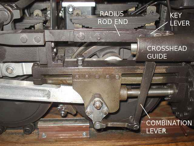 - Image 222 -- New Radius Rod End
I am using the old crossheads, guides, and combination levers. But the radius rod ends needed to be replaced so as to connect to the new key levers seen in the photo. The key levers pass the return crank motion directly to the exhaust valve rods. I had to modify the crosshead guides to make clearance for two valve rods where only one was required previously. This entailed milling a vertical obround inside the guides where a round bore was needed before. 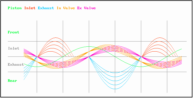 - Image 223 -- New Valve Timing
Inlet timing is controlled by the combination lever (as before). But exhaust timing is now controlled by the return crank only. This allows the inlet timing to be optimized while the exhaust valve is open for [almost] the entire return stroke. Here's a summary of improvements:
11/19/13 - Running with the New ValvesI have never seen a smoother running steam engine ever. It is a joy to operate. The new valves meet and exceed my expectations. The following is a video made after the modifications. Enjoy...
(Back to Page 33) (On to Page 35)
Bill |