Steam Locomotive, Page 4(Back to Page 3) 4/13/2 Two more large castings are called "saddle halfs" because two of them bolted back-to-back form the "saddle". The saddle holds up the smokebox and one end of the boiler, and must support the weight of the cylinders.
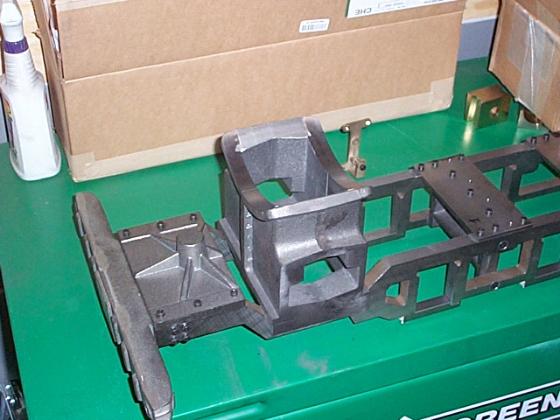 Image 10. Saddle, Front Deck, Pilot Beam, Frame Plate Here's another view. Note the object in the background is a "brake hanger". It was cast from silicon bronze, and 4 of them bolt to the outside of each frame. They support the arm that holds a brake shoe for each wheel.
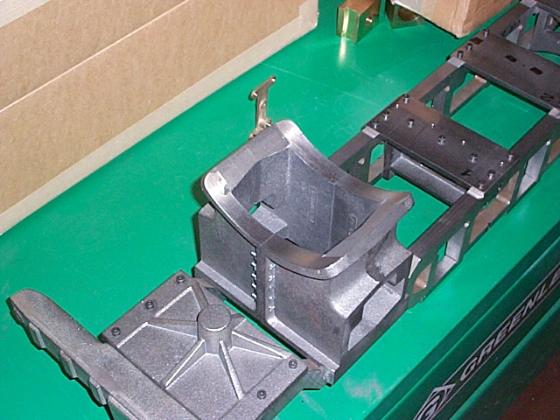
Image 11: Another view The next major task is to build the cylinders. These start out as very heavy iron castings. To complete them the builder must machine the faces to specification, and drill and sometimes tap a large number of holes.
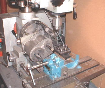
Image 12: Cylinder machining What you see in these photos is the valve cylinder being bored. Boring can be done either with the drill press, or on the lathe. Because the length of the cylinders is five inches, and the travel on my drill press is only three and one half, I really only had one choice. Here, the casting is mounted on a faceplate. Note the counterweights used to help balance the faceplate.
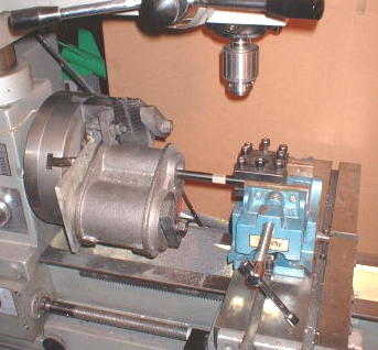
Image 13: Cylinder Machining Once all the facing, drilling, boring, and tapping is done, the cylinders can be assembled with the saddle, and the plumbing connected. The following photo shows two brass manifolds connected to the exhaust pipes.
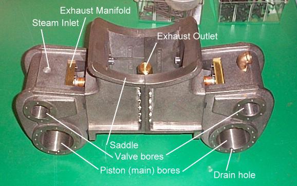
Image 14: Completed Cylinders and Saddle
(On to Page 5) |