Steam Locomotive, Page 6(Back to Page 5) It's time to fasten on the wheels and quarter them on the axles. But first, lets see how the bearing is assembled. The bearing-block is constructed per the suppliers drawings and procedure described on his website with the following exceptions. 1. Aluminum bronze was used instead of cast iron. 2. The outside opening was enlarged to accomodate the wheel spacer, which is not called for in the drawings. 3. All extra lateral travel is built into the frame slots. 4. Forego all "hourglass" shaping of the frame slots except on #3, as widening the slots on the other axles for extra travel achieves the same goal. 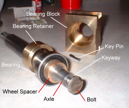
Image 18: Bearing assembly - This engine is being regauged to 7.25" which gives only 0.060" clearance between axlebox and the back of each wheel. The original drawings call for 0.063" of lateral travel in axles #2 aand #4, and 0.125" in axle #1. This already exceeds the clearance available. So all extra travel must be built into the frame slots. The "bearing retainer" holds the bearing against the block, and the "wheel spacer" prevents the wheel from running into the bearing block. 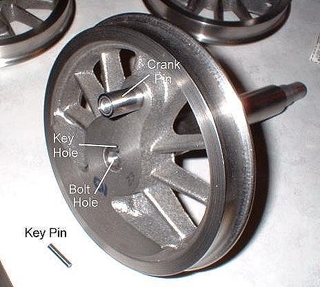
Image 19: Quartering and Securing Detail - Note: Always use a carbide drill for this. Otherwise the differences in hardness between wheel and axle will cause the drill to "drift". It still works, but doesn't look very good. Bolting the wheels on? I like to be able to remove wheels at any time. These bolts sure make it easy. An alternative fastening method is to drill and tap a setscrew hole into each wheel hub and on into the axle and drive a long stainless steel setscrew into both wheel and axle. I did this on my gas-electric locomotive. 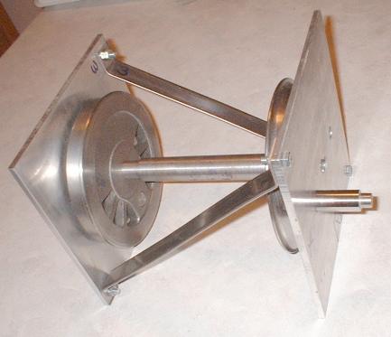
Image 20: Quartering Frame - (On to Page 7) |