Air Tender
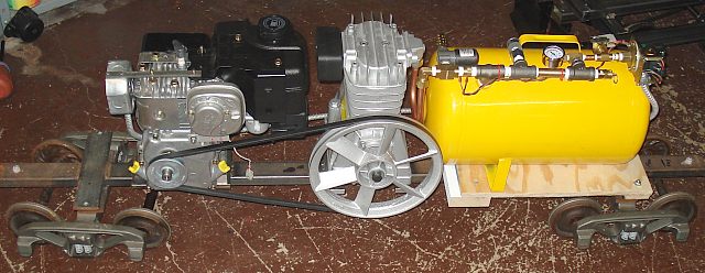
Image 1: Completed Air Tender Chassis The Air Tender is an air compressor in a boxcar powered by a gasoline engine. Visit my Boxcar Construction Page for details about the boxcar. It's actually an ice bunker refrigerator car. But for all practical purposes - a boxcar.
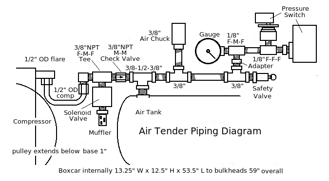
Image 2: Piping Diagram The compressor is piped to a solenoid valve, check valve, air tank, safety valve, gauge, two pressure switches, and finally an air chuck to connect to the locomotive via a long air hose.
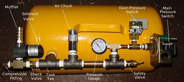
Image 3: Tank and it's associated accessories When the solenoid valve is closed, air from the compressor is forced through the check valve and into the air tank. The check valve prevents tank air from exiting through the solenoid valve when it is energized. Below operating pressure, the main pressure switch closes, opening a relay that otherwise supplies power to the unloader valve and throttle control solenoids. This allows the tank to fill and the engine to run at governor speed.
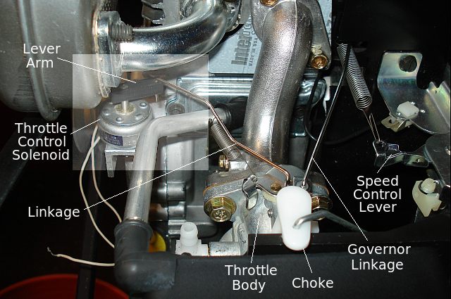
Image 4: Throttle Control Solenoid (Fuel tank removed) When operating pressure is reached the pressure switch opens, closing the relay powering the solenoid valve and throttle control solenoid unloading the compressor and forcing the engine to minimum throttle. A second pressure switch, which is set to a limit slightly higher than the main pressure switch, kills the engine if ever closes.
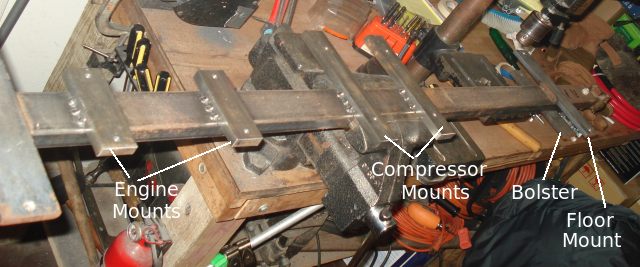
Image 4: Frame Modifications The boxcar frame had to be modified to support the engine and compressor. Sure it is possible to just bolt these to the boxcar floor, but I'm afraid the wooden box will amplify the noise generated by this equipment. I'm hoping that mounting to the frame will reduce this tendancy.
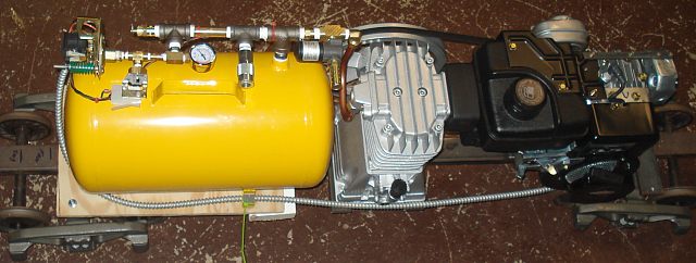
Image 5: Electrical Cable Here's the completed compressor minus the carbody and battery, which has not arrived yet. Both units now have oil in them. The control wires between the engine and the air tank are contained in this armoured cable jacket. This mostly just functions as a conduit for the wires but does offer them lots of protection.
Wiring
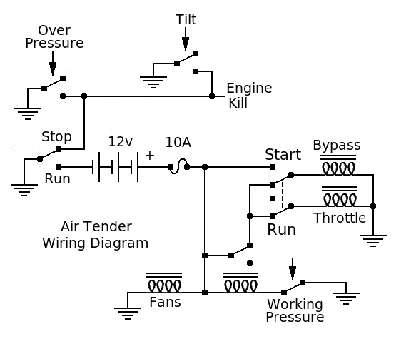
Image 6: Wiring Diagram The wiring is quite simple. A 12 volt sealed lead-acid battery is needed to power the relay, solenoids, and fans. Fans are needed to evacuate the boxcar of engine cooling air. A tilt switch, second pressure switch, and a toggle switch are provided to kill the engine in the event of a derailment, overpressure situation, or as needed by the engineer. A second switch was added to aid in starting by allowing the engine to operate above idle with no load. The fuse is not optional. You've read the book. Now go see the movie...
Other ItemsA generator could be added to maintain the battery. Also, interior lighting will be helpful if you plan to operate at night. An electrical outlet would allow operating the locomotive electrical system without an extra battery in the engine or tender.
Parts List
|