Page Two
-
Air Horns
There are two kinds of air horns. Those that toot, and those that don't.
-
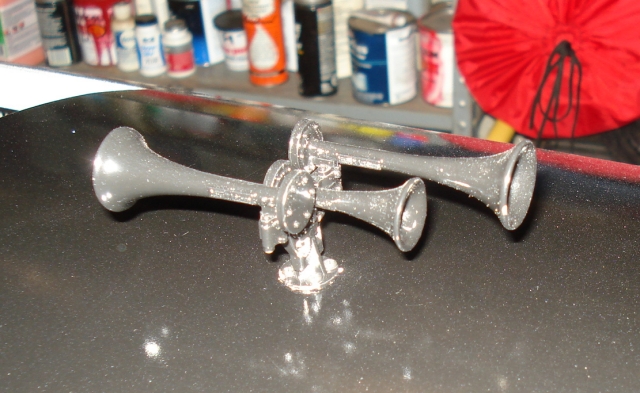 Image 14 - Air Horns for Show
These don't toot. But they do look nice. These came from Precision Steel Car
Company of Hamilton, Ohio. They are investment castings. It is true that F7s
did not come with Nathan 3 chimes. But it was also true back in the steam
days that an engineer could install any whistle or bell he wanted as long as
it met the letter of the law. I don't know how far into the diesel days that
carried.
-
Image 14 - Air Horns for Show
These don't toot. But they do look nice. These came from Precision Steel Car
Company of Hamilton, Ohio. They are investment castings. It is true that F7s
did not come with Nathan 3 chimes. But it was also true back in the steam
days that an engineer could install any whistle or bell he wanted as long as
it met the letter of the law. I don't know how far into the diesel days that
carried.
-
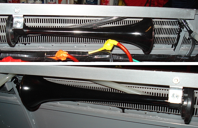 Image 15 - Air Horns that Blow
These horns DO toot - and in a very big way. They are both installed facing
forward behind the radiator grilles, one on each side. They are connected by
an air hose to the compressor.
These trumpets as purchased are bright red. That would look very bad from the
outside so I toned them down by painting them black.
Image 15 - Air Horns that Blow
These horns DO toot - and in a very big way. They are both installed facing
forward behind the radiator grilles, one on each side. They are connected by
an air hose to the compressor.
These trumpets as purchased are bright red. That would look very bad from the
outside so I toned them down by painting them black.
The Relay Box
-
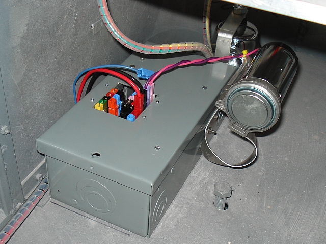 Image 16 - Relay Box Location
The compressor mounted to the relay box and the air hose is connected. Notice
my custom patented anti-noise coupling compressor mount. It's made from a
piece of scrap aluminum left over from a roof or hatch cutout.
-
Image 16 - Relay Box Location
The compressor mounted to the relay box and the air hose is connected. Notice
my custom patented anti-noise coupling compressor mount. It's made from a
piece of scrap aluminum left over from a roof or hatch cutout.
-
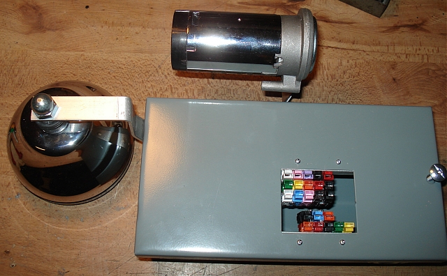 Image 26 - Relay Box
The Relay Box contains the main relay, horn relay, and a hand wired circuit
board which controls the horn, bell, and head lights. There are numerous
connectors which attach to various wiring harnessed within the locomotive.
The bell and horn compressor are attached to the outside of the relay box.
The compressor is mounted with a special spring that was designed to support
the compressor without transmitting the sound from it to the chassis.
-
Image 26 - Relay Box
The Relay Box contains the main relay, horn relay, and a hand wired circuit
board which controls the horn, bell, and head lights. There are numerous
connectors which attach to various wiring harnessed within the locomotive.
The bell and horn compressor are attached to the outside of the relay box.
The compressor is mounted with a special spring that was designed to support
the compressor without transmitting the sound from it to the chassis.
-
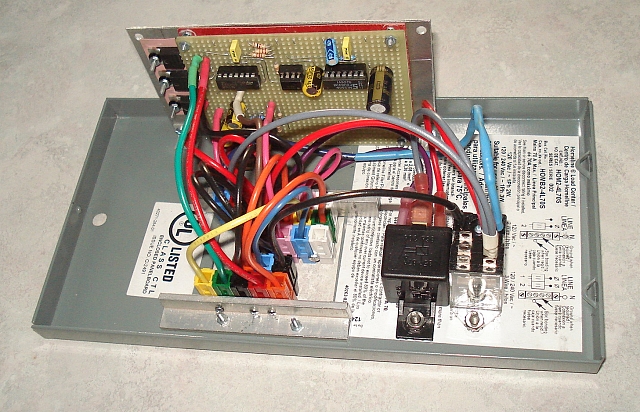 Image 27 - Inside the Relay Box
Here's a view inside the relay box showing the components I described above.
You can view Schematic Diagrams for everything on this page by following the link.
Here are schematics and such for the Radio Control interface.
Image 27 - Inside the Relay Box
Here's a view inside the relay box showing the components I described above.
You can view Schematic Diagrams for everything on this page by following the link.
Here are schematics and such for the Radio Control interface.
The Handheld Radio Control Box
-
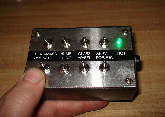 Image 22 - Handheld Radio
This is a wireless handheld control box. Functions match the wired version
shown below. It uses a Zigbee radio and is networked to a receiver inside
the locomotive's steam hatch. Both the handheld and locomotive based
endpoints are now fully operational.
I must hold the unit as shown in order to power it up. That is a safety
feature. If I fail to hold the unit properly, the locomotive will go into
dynamic braking.
Page 3
Image 22 - Handheld Radio
This is a wireless handheld control box. Functions match the wired version
shown below. It uses a Zigbee radio and is networked to a receiver inside
the locomotive's steam hatch. Both the handheld and locomotive based
endpoints are now fully operational.
I must hold the unit as shown in order to power it up. That is a safety
feature. If I fail to hold the unit properly, the locomotive will go into
dynamic braking.
Page 3
|