-
Image 1 - Prototype Photo
This is actually the prototype locomotive manufacturer's publicity photo
published many years ago. But this is also the paint scheme I am using.
-
Here is a short video of the first run...
We got word that Jim Murray, owner of MDM Locomotive Works passed away on
May 6th. The body of this F7 was a kit from MDM and very likely the the last
one sold by Jim Murray. There is no word of what will become of the company.
-
Image 2 - My F7 before Paint
And this is an actual photo of the 1/8th scale EMD F7A that I built prior to
painting it. The "kit" consists of a pile of aluminum and sheet steel and a
bunch of drawings with a note that says "good luck". There was also some
pre-made items and a couple boxes of loose parts.
The battery box, fuel tank, exhaust stacks, and pilot come pre-built. Castings
include the "A" end (cab), the "B" end (wall) and steps, anticlimbers, the
number boxes, stirrup steps, sand hatches, fan grilles, roof braces, hatch
braces, and a buffer block.
You also get six stamped and formed radiator grilles, side grille plates, tank
skirt stock, and roof and hatch sheets that are rolled and formed (more or
less) to the approximate shape. But the rest is totally up to the builder. To
complete one of these requires machining and a huge amount of hard work.
To the credit of MDM locomotive and Jim Murray, if you have one of these and
have done a good job building and painting it, you will only get massively
favorable comments. Everyone who has seen it in person was totally amazed.
-
Image 3 - F7A Floor
The frame consist of twin I beams and the floor is 1/8" sheet steel. The
bolster plates are welded across the I beams. The coupler brackets are welded
to each end of the frame box. Here the assembly has been painted primer white.
Disclaimer...
The electronics and trucks you see in this article were not supplied by MDM.
Truck castings came from Tom Bee. Drive hardware and all electronics were
supplied by me. I made other modifications from the original kit plans too.
-
Image 4 - Fan Cover Variation
For example: The radiator fan hatches have 3 braces. One at each end, and one
in the center. These support the fan mounting plate. The kit instructions say
to cut out 6 notches in the hatch cover to clear the braces.
Not me. I milled reliefs in the ends of the 3 braces to clear the tabs in the
hatch covers. It's easier, neater, and looks better. The braces already need
to be machined. So what's one extra step?
-
Image 5 - Pilot Mounting Deviation
Here's another modification I made. The kit instructions say to mount the
pilot to the coupler pocket supports using two brackets provided. They also
provide material to make braces to stiffen the assembly up.
That's a lot of work in a mostly inaccessible area. Additionally, the coupler
pocket mount is not the most robust structure either. So instead, I mounted
the pilot to the floor using these four large standoffs. Easy, rugged, done.
-
Image 6 - Vinyl Kick Plates
Kick plate material is supplied by the kit manufacturer in the form of
stainless steel shim stock. These have to be cut out precisely and adhered
to the body with epoxy. That's a lot of work and it's hard to make it look
right. So I just ordered them in cut silver vinyl and put them on.
-
Image 7 - Nose Herald
While on the subject of vinyl, I waited over a month to get this nose herald.
I requested a quote from a vinyl supplier that I normally use. I got no reply.
So I tried another vendor. After two weeks waiting it arrived with the colors
backwards. So I went back to the original supplier, paid too much, but finally
got it.
Vinyl Suppliers
Kick Plates: Speedesigns
Nose Herald: Words Anywhere
Side Lettering: Words Anywhere
Number Boards: DIY Lettering
No. The wings and stripes are NOT vinyl. Those were all painted on.
Chassis Lighting
-
Image 8 - Headlight Mounting
The two head lamps are mounted on a plate in the nose of the F7. They are
tungsten halogen - 55 watts each. This mounting method and choice of lamps
requires replacing the acrylic lens material supplied with borosilcate glass.
-
Image 9 - Number Board Lighting
The number boards each use 3 "bullet" instrument lamps. You can see them
here inside the lamp box with one of the number boards removed. This also
is a deviation from kit recommendations. My lamp boxes are half the size
of those in the drawings.
The classification lights are simple push-in plastic lamps. This too is a
modification. However, the lamp mounts are pretty much per the drawing.
-
Image 10 - Number Board Lamp Boxes
From inside the nose, the number board lamps can't be seen. They are under that
copper strip which is held to the lamp box with nylon (insulating) bolts. The
under side of the copper strip is tinned (with solder) where it contacts the 3
lamps to give the lamps a good electrical contact.
-
Image 11 - Number Boards - Lit
A view of the number boards in operation. The "kit" comes with opaque white
acrylic to use for number boards with the intention of applying the numbers
to the outside.
Instead I used clear polycarbonate and ordered black cut vinyl numbers with
a negative or reverse weed. The vinyl was applied to the inside. Thin white
acetal sheet was applied over that to act as a diffuser.
-
Image 12 - Classification Lights
A view of the classification lights in operation.
-
Image 13 - Pilot and Paint Can
Here's a quick photo showing the nose door, pilot and front coupler in front
of that paint can.
Page 2
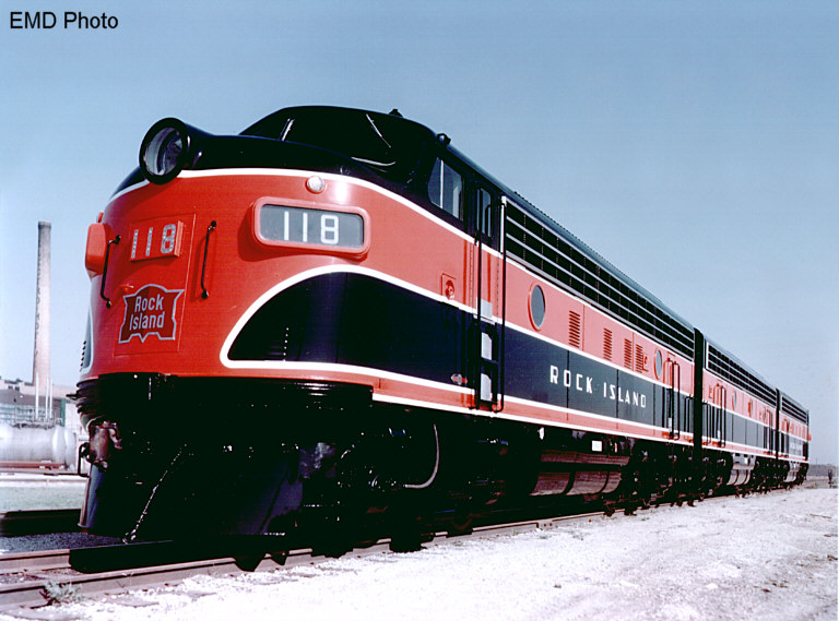 Image 1 - Prototype Photo
This is actually the prototype locomotive manufacturer's publicity photo
published many years ago. But this is also the paint scheme I am using.
-
Here is a short video of the first run...
We got word that Jim Murray, owner of MDM Locomotive Works passed away on
May 6th. The body of this F7 was a kit from MDM and very likely the the last
one sold by Jim Murray. There is no word of what will become of the company.
-
Image 1 - Prototype Photo
This is actually the prototype locomotive manufacturer's publicity photo
published many years ago. But this is also the paint scheme I am using.
-
Here is a short video of the first run...
We got word that Jim Murray, owner of MDM Locomotive Works passed away on
May 6th. The body of this F7 was a kit from MDM and very likely the the last
one sold by Jim Murray. There is no word of what will become of the company.
-
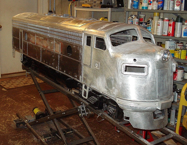 Image 2 - My F7 before Paint
And this is an actual photo of the 1/8th scale EMD F7A that I built prior to
painting it. The "kit" consists of a pile of aluminum and sheet steel and a
bunch of drawings with a note that says "good luck". There was also some
pre-made items and a couple boxes of loose parts.
The battery box, fuel tank, exhaust stacks, and pilot come pre-built. Castings
include the "A" end (cab), the "B" end (wall) and steps, anticlimbers, the
number boxes, stirrup steps, sand hatches, fan grilles, roof braces, hatch
braces, and a buffer block.
You also get six stamped and formed radiator grilles, side grille plates, tank
skirt stock, and roof and hatch sheets that are rolled and formed (more or
less) to the approximate shape. But the rest is totally up to the builder. To
complete one of these requires machining and a huge amount of hard work.
To the credit of MDM locomotive and Jim Murray, if you have one of these and
have done a good job building and painting it, you will only get massively
favorable comments. Everyone who has seen it in person was totally amazed.
-
Image 2 - My F7 before Paint
And this is an actual photo of the 1/8th scale EMD F7A that I built prior to
painting it. The "kit" consists of a pile of aluminum and sheet steel and a
bunch of drawings with a note that says "good luck". There was also some
pre-made items and a couple boxes of loose parts.
The battery box, fuel tank, exhaust stacks, and pilot come pre-built. Castings
include the "A" end (cab), the "B" end (wall) and steps, anticlimbers, the
number boxes, stirrup steps, sand hatches, fan grilles, roof braces, hatch
braces, and a buffer block.
You also get six stamped and formed radiator grilles, side grille plates, tank
skirt stock, and roof and hatch sheets that are rolled and formed (more or
less) to the approximate shape. But the rest is totally up to the builder. To
complete one of these requires machining and a huge amount of hard work.
To the credit of MDM locomotive and Jim Murray, if you have one of these and
have done a good job building and painting it, you will only get massively
favorable comments. Everyone who has seen it in person was totally amazed.
-
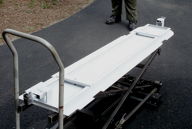 Image 3 - F7A Floor
The frame consist of twin I beams and the floor is 1/8" sheet steel. The
bolster plates are welded across the I beams. The coupler brackets are welded
to each end of the frame box. Here the assembly has been painted primer white.
Image 3 - F7A Floor
The frame consist of twin I beams and the floor is 1/8" sheet steel. The
bolster plates are welded across the I beams. The coupler brackets are welded
to each end of the frame box. Here the assembly has been painted primer white.
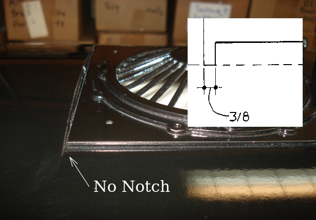 Image 4 - Fan Cover Variation
For example: The radiator fan hatches have 3 braces. One at each end, and one
in the center. These support the fan mounting plate. The kit instructions say
to cut out 6 notches in the hatch cover to clear the braces.
Not me. I milled reliefs in the ends of the 3 braces to clear the tabs in the
hatch covers. It's easier, neater, and looks better. The braces already need
to be machined. So what's one extra step?
-
Image 4 - Fan Cover Variation
For example: The radiator fan hatches have 3 braces. One at each end, and one
in the center. These support the fan mounting plate. The kit instructions say
to cut out 6 notches in the hatch cover to clear the braces.
Not me. I milled reliefs in the ends of the 3 braces to clear the tabs in the
hatch covers. It's easier, neater, and looks better. The braces already need
to be machined. So what's one extra step?
-
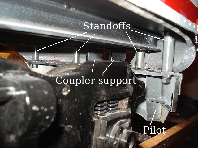 Image 5 - Pilot Mounting Deviation
Here's another modification I made. The kit instructions say to mount the
pilot to the coupler pocket supports using two brackets provided. They also
provide material to make braces to stiffen the assembly up.
That's a lot of work in a mostly inaccessible area. Additionally, the coupler
pocket mount is not the most robust structure either. So instead, I mounted
the pilot to the floor using these four large standoffs. Easy, rugged, done.
-
Image 5 - Pilot Mounting Deviation
Here's another modification I made. The kit instructions say to mount the
pilot to the coupler pocket supports using two brackets provided. They also
provide material to make braces to stiffen the assembly up.
That's a lot of work in a mostly inaccessible area. Additionally, the coupler
pocket mount is not the most robust structure either. So instead, I mounted
the pilot to the floor using these four large standoffs. Easy, rugged, done.
-
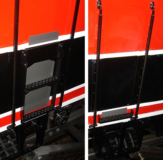 Image 6 - Vinyl Kick Plates
Kick plate material is supplied by the kit manufacturer in the form of
stainless steel shim stock. These have to be cut out precisely and adhered
to the body with epoxy. That's a lot of work and it's hard to make it look
right. So I just ordered them in cut silver vinyl and put them on.
-
Image 6 - Vinyl Kick Plates
Kick plate material is supplied by the kit manufacturer in the form of
stainless steel shim stock. These have to be cut out precisely and adhered
to the body with epoxy. That's a lot of work and it's hard to make it look
right. So I just ordered them in cut silver vinyl and put them on.
-
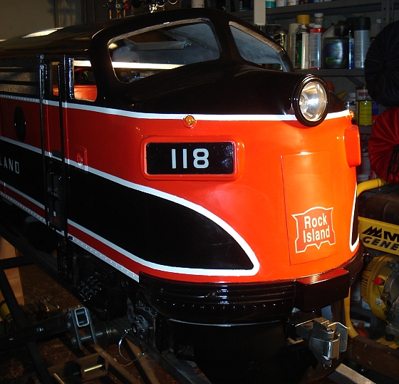 Image 7 - Nose Herald
While on the subject of vinyl, I waited over a month to get this nose herald.
I requested a quote from a vinyl supplier that I normally use. I got no reply.
So I tried another vendor. After two weeks waiting it arrived with the colors
backwards. So I went back to the original supplier, paid too much, but finally
got it.
Vinyl Suppliers
Kick Plates: Speedesigns
Nose Herald: Words Anywhere
Side Lettering: Words Anywhere
Number Boards: DIY Lettering
No. The wings and stripes are NOT vinyl. Those were all painted on.
Image 7 - Nose Herald
While on the subject of vinyl, I waited over a month to get this nose herald.
I requested a quote from a vinyl supplier that I normally use. I got no reply.
So I tried another vendor. After two weeks waiting it arrived with the colors
backwards. So I went back to the original supplier, paid too much, but finally
got it.
Vinyl Suppliers
Kick Plates: Speedesigns
Nose Herald: Words Anywhere
Side Lettering: Words Anywhere
Number Boards: DIY Lettering
No. The wings and stripes are NOT vinyl. Those were all painted on.
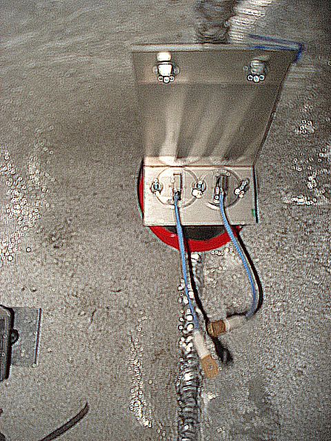 Image 8 - Headlight Mounting
The two head lamps are mounted on a plate in the nose of the F7. They are
tungsten halogen - 55 watts each. This mounting method and choice of lamps
requires replacing the acrylic lens material supplied with borosilcate glass.
-
Image 8 - Headlight Mounting
The two head lamps are mounted on a plate in the nose of the F7. They are
tungsten halogen - 55 watts each. This mounting method and choice of lamps
requires replacing the acrylic lens material supplied with borosilcate glass.
-
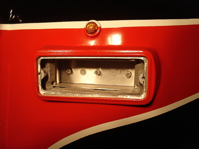 Image 9 - Number Board Lighting
The number boards each use 3 "bullet" instrument lamps. You can see them
here inside the lamp box with one of the number boards removed. This also
is a deviation from kit recommendations. My lamp boxes are half the size
of those in the drawings.
The classification lights are simple push-in plastic lamps. This too is a
modification. However, the lamp mounts are pretty much per the drawing.
-
Image 9 - Number Board Lighting
The number boards each use 3 "bullet" instrument lamps. You can see them
here inside the lamp box with one of the number boards removed. This also
is a deviation from kit recommendations. My lamp boxes are half the size
of those in the drawings.
The classification lights are simple push-in plastic lamps. This too is a
modification. However, the lamp mounts are pretty much per the drawing.
-
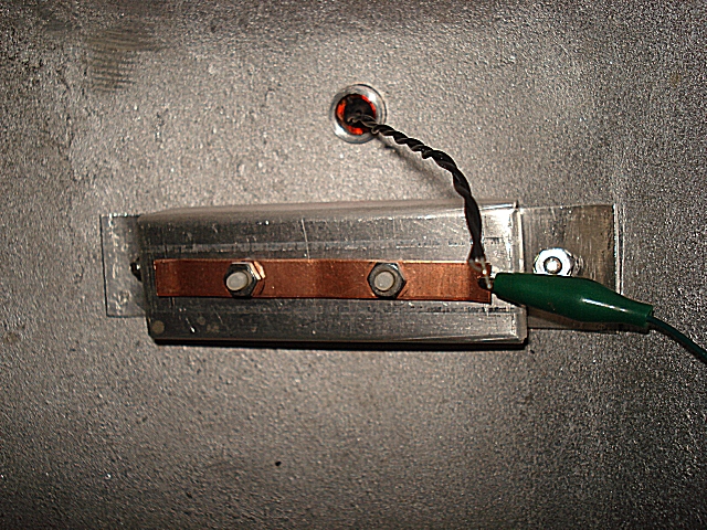 Image 10 - Number Board Lamp Boxes
From inside the nose, the number board lamps can't be seen. They are under that
copper strip which is held to the lamp box with nylon (insulating) bolts. The
under side of the copper strip is tinned (with solder) where it contacts the 3
lamps to give the lamps a good electrical contact.
-
Image 10 - Number Board Lamp Boxes
From inside the nose, the number board lamps can't be seen. They are under that
copper strip which is held to the lamp box with nylon (insulating) bolts. The
under side of the copper strip is tinned (with solder) where it contacts the 3
lamps to give the lamps a good electrical contact.
-
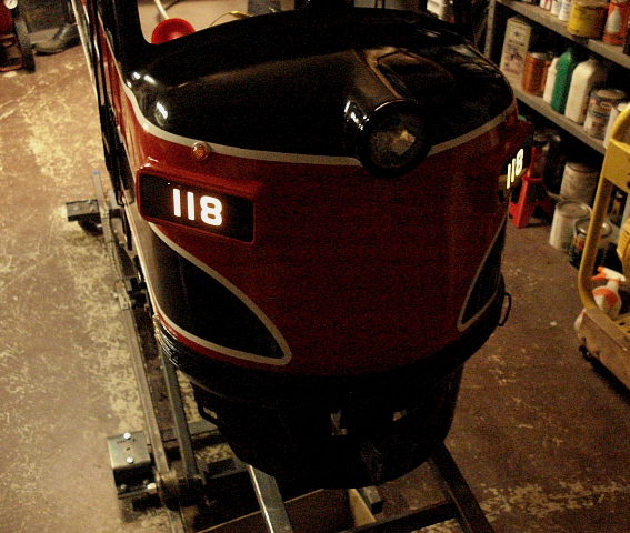 Image 11 - Number Boards - Lit
A view of the number boards in operation. The "kit" comes with opaque white
acrylic to use for number boards with the intention of applying the numbers
to the outside.
Instead I used clear polycarbonate and ordered black cut vinyl numbers with
a negative or reverse weed. The vinyl was applied to the inside. Thin white
acetal sheet was applied over that to act as a diffuser.
-
Image 11 - Number Boards - Lit
A view of the number boards in operation. The "kit" comes with opaque white
acrylic to use for number boards with the intention of applying the numbers
to the outside.
Instead I used clear polycarbonate and ordered black cut vinyl numbers with
a negative or reverse weed. The vinyl was applied to the inside. Thin white
acetal sheet was applied over that to act as a diffuser.
-
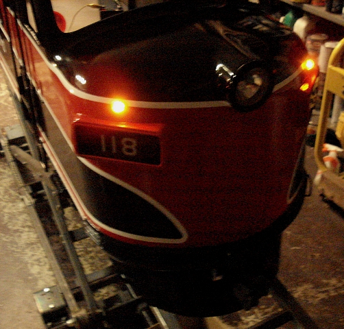 Image 12 - Classification Lights
A view of the classification lights in operation.
-
Image 12 - Classification Lights
A view of the classification lights in operation.
-
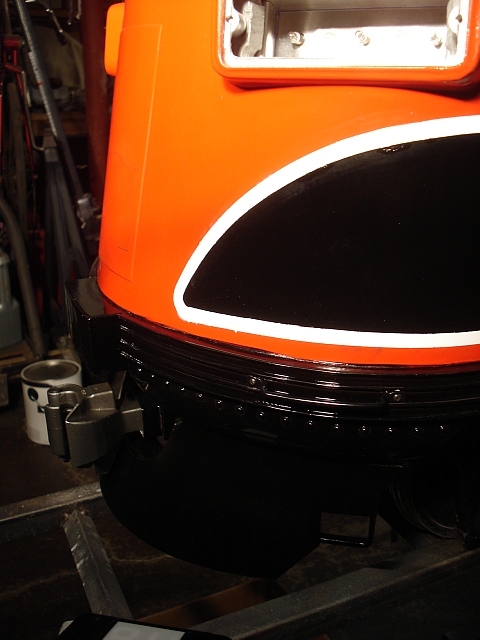 Image 13 - Pilot and Paint Can
Here's a quick photo showing the nose door, pilot and front coupler in front
of that paint can.
Image 13 - Pilot and Paint Can
Here's a quick photo showing the nose door, pilot and front coupler in front
of that paint can.