The NB2 Locomotive(by Island Pond Railroad)
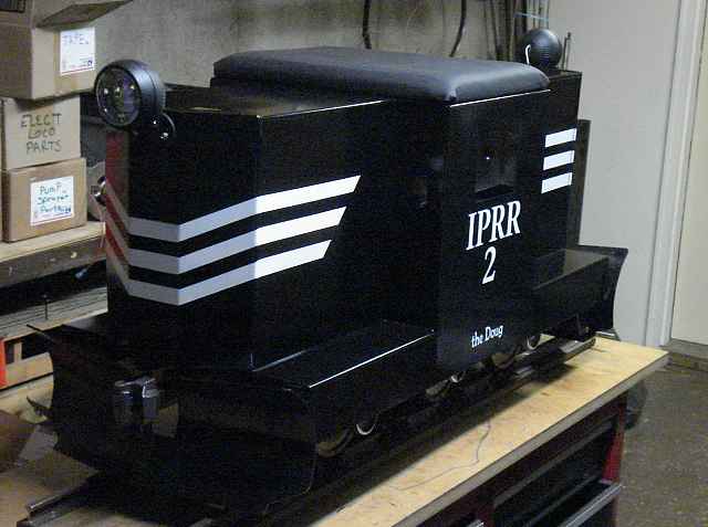
- The NB2 Locomotive All photos on this page are from an early configuration of the NB2. You can see the updates on the Changes page. This is the prototype for a locomotive that Doug, one of my twin sons, built a few years ago as a possible "build-to-sell" project. He ended up moving to Pennsylvania, and this is the only one we built. The NB2 is now fully operational. It's shell is made entirely of sheet steel (compared to the NB1 which was all plywood). The shell consists of only three basic parts which houses four sub-assemblies. I tried to make the stripes on the NB2 the same as those on the NB1 but because the noses are shaped differently, the pattern didn't fit or look right. So this is an adaptation of the scheme to fit the GP9 style nose.
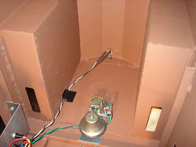 Inside the Body Shell A little piece of Gorilla Tape holds the headlight wiring in place. You can see the bell wiring also going back to the switch panel. Notice how the nose pieces resemble a "GP9" nose. 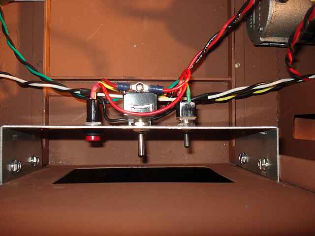 Horn, Headlight, and Bell Switches The horn, bell, and headlight switches are accessed by the engineer through the cab window on the left side of the locomotive. 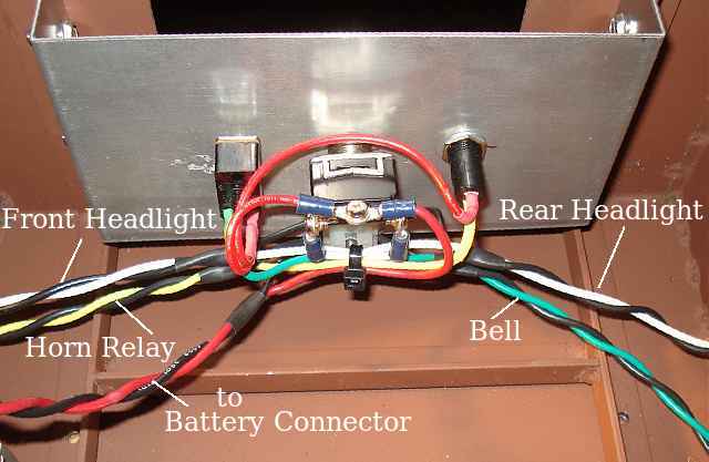 Another view Shown here is the wiring to the various electrical appliances. 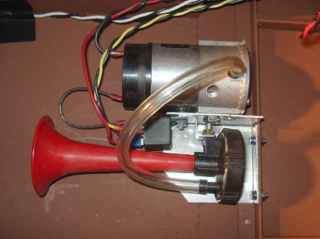 Horn and Compressor Bracket. The air horn, it's compressor, and relay are all mounted on one bracket which is attached to one of the engineer's seat supports. The entire assembly can be removed easily for servicing. 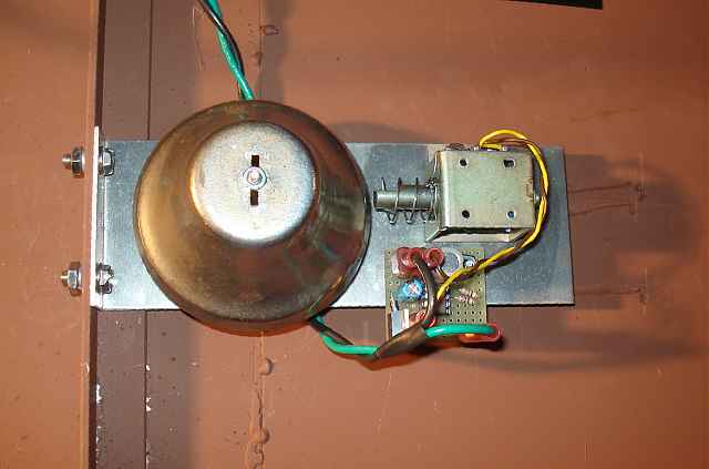 Bell, Ringer Solenoid, and Ringer Circuit The bell is made from an old handbell from a surplus store. The solenoid came from an 8-track tape player. The circuit uses a 555 timer and a P-channel MOSFET. The bracket is attached to one of the engineer's seat supports.
The Frame
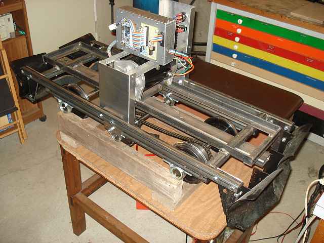 Left side view of the Locomotive Chassis 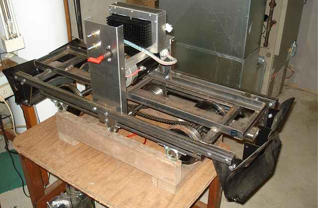 Right side view of the Locomotive Chassis 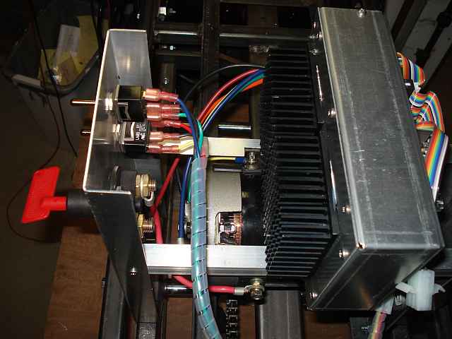 Looking behind the Right Side Switch Panel 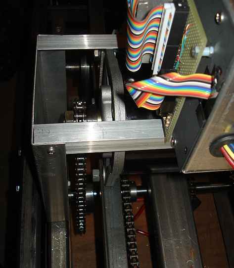 The motor and chain drive to the Output Shaft You can also see the chains going between the output shaft and the two axles. 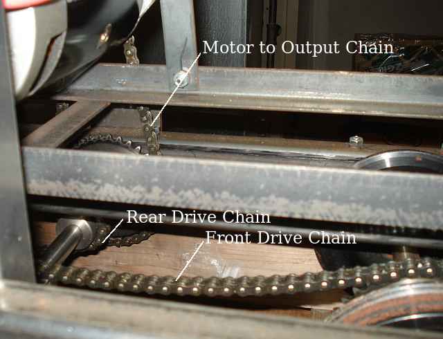 Another view of the drive chains
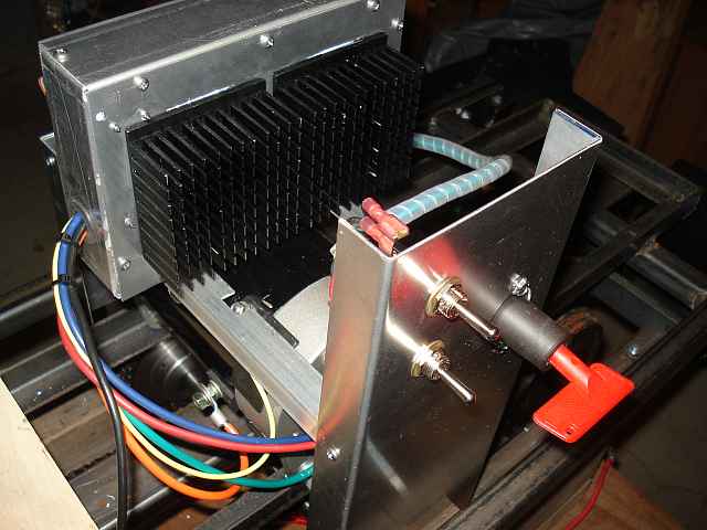 Controller and Control Panel The controller chassis sits on a pair of rails over the motor. The switch panel is accessed by the engineer through the right side cab window. It holds the main power switch as well as the throttle and dynamic brake switches. A train line switch was added after this photo was taken. 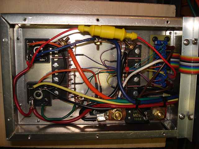 Inside the electrical chassis This chassis houses the high current (100 amp) circuits. In this box are eight 250 amp N-channel power MOSFETs. The bridge rectifiers must handle the motor load after the MOSFET switches turn off. These would later be replaced with big diodes. Notice there are NO relays. 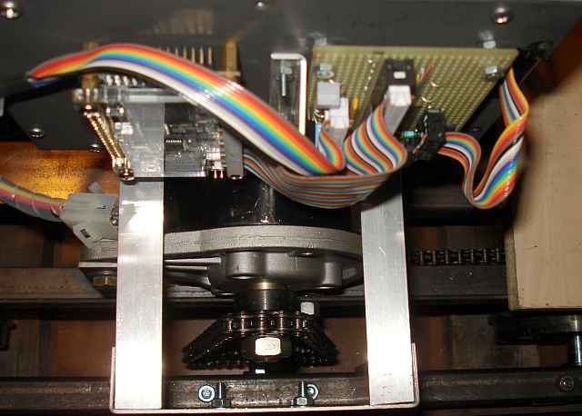 FPGA and Analog boards plus Motor and Chain A steel plate covers the high current components. This is necessary because it is a magnetic and electrostatic shield. It isolates the sensitive FPGA and analog boards (mounted on it) from large current spikes caused by switching. 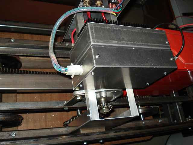 FPGA and Analog Board Cover And finally an aluminum cover over the circuit boards completes the controller package. The following is a short video showing the operation of the locomotive with the carbody removed.
For the geeks:
View the NB2 firmware source file HERE. The following is a short video showing Ken operating the locomotive over the railroad.
All photos on this page are from an early configuration of the NB2. You can see the updates on the Changes page. Bill. |