Steam Locomotive -- page 20(Back to Page 19) 12/1/6 -- December already here? - Ugh! 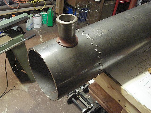
Image 109 -- Boiler shell and Smokebox joined! The joining ring is now finished and the smokebox and boiler shell are attached. I will have to take this apart to deburr the ring (lots of sharp objects inside makes it unsafe to work). I should also grind off the tops of the stack mounting bolts. I like using these stainless steel round Phillips head screws because they look like the rivets used by the prototype locomotive. 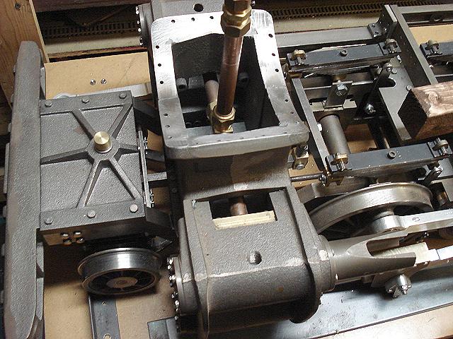
Image 110 -- Looking down at the exhaust pipe It's been almost 4 years since I last had the smokebox off. But while it's off let's have a look at the exhaust fittings. These are all 1/2" compression fittings. A Tee and a plug on top. That plug will be drilled to give the desired draft and sound. 12/4/6 -- Fire Door 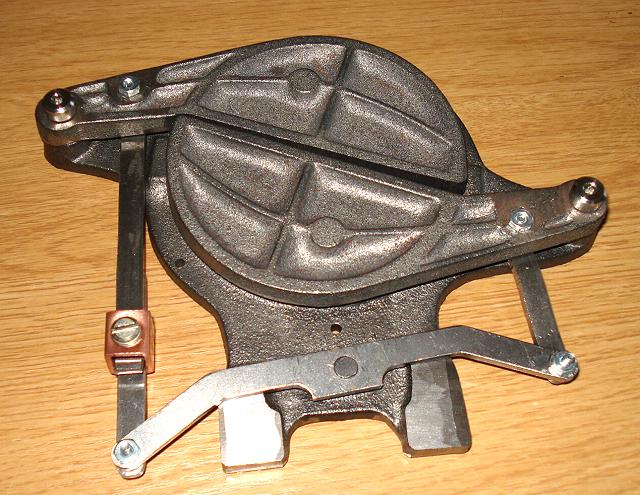
Image 111 -- Firebox Door - Closed Take all those wonderful Firedoor drawings and toss them into the firebox with a lit match. They are useless. The kit supplier admits (in an E-mail message) that he never built one. It can't possibly work. The lower door collides with the levers after only opening a fraction of an inch. No good. 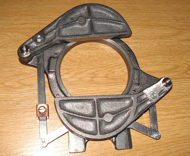
Image 112 -- Firebox Door - Open Replace all those rods and clevises with these simple bars and only use one lever. Position it so that it can operate behind the lower door. You'll also have to grind away the lever plate feet. This screw clamp adjuster is a cheap hardware store item that can be found in the electrical section. Adjust the link so that the doors close properly. These screws are only temporary. I ordered 1/8" rivets to replace them. 12/11/6 -- Boiler-top Detail Mounting 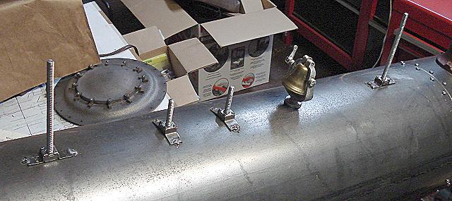
Image 113 -- Weldnuts and Studs These are called "weld nuts" because you just weld them down as I have done. The nuts are loose inside their little holders so that they can align to the studs. The studs are 1/4"-20 threaded rod. 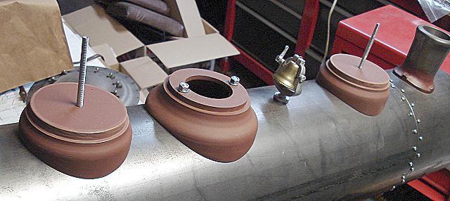
Image 114 -- Dome Bases in Place Holes are drilled through the bases for the studs. This is the kit supplier's recommended mounting method, even though the drawings say nothing about it. 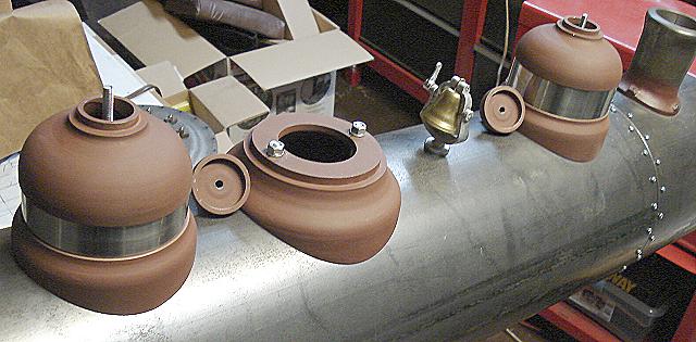
Image 115 -- Domes Minus Lids Then sand dome lids are drilled and tapped to thread onto the ends on the studs protruding through the domes. The lids hold the entire dome together and in place. 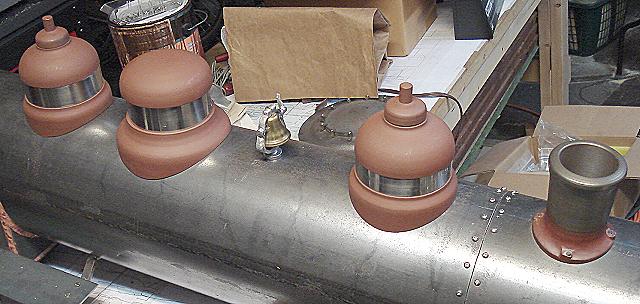
Image 116 -- Lids On The steam dome is only held on by gravity. I need to come up with a more positive method, but must wait to see what need to go into the dome first. The bell, bolted on top Is from Cannonball. It is too small and in the wrong place. It will later get replaced with Lady Liberty. (On to Page 21) |