90 Ton Mikado, Page 22Back to Page 21 7/31/7 -- Time for some Valve work! 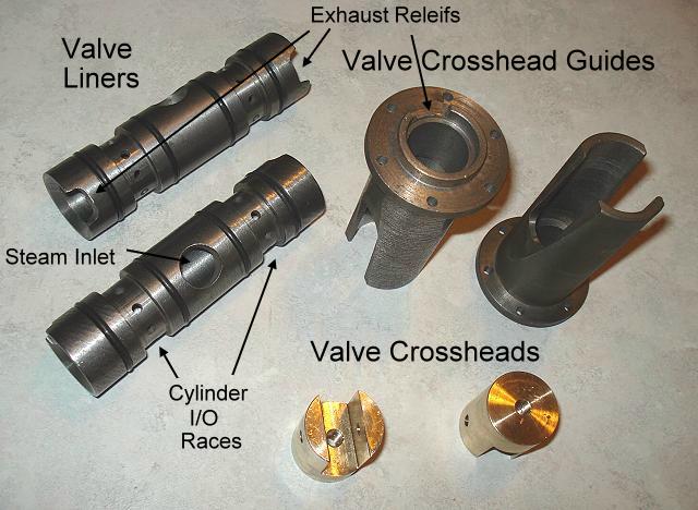
Image 123 -- Valve Liners, Crossheads, and Guides Yes, I know, you've seen the crosshead guides before. But now they are off the locomotive so that the crossheads can be fitted to them. The guides mount to the rear of the valve bore and hold the liners in the bores. The exhaust reliefs in the guides match the reliefs in the liners, and line up with the exhaust airways drilled in the valve bores. The crossheads run inside the guides. The drawings call for the cylinder inlet/outlet races to be cut into the cylinder bores. But that's just too much trouble for me. My solution is to cut them into valve liners instead. This requires that the liners now be thicker, and the valves be smaller, but as long as they can handle the same steam volume, I am not going to worry about it. Also not included on the drawings are the o-rings to keep the steam from running between the liners and bores. 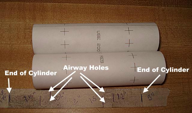
Image 124 -- Template for Valve Liners So how did I drill all those holes in the valve liners for the airway races? I made a template. First, I had to see where the airway holes were in the cylinder assembly by putting a piece of masking tape inside the length of the cylinder over the airway holes. I then ran my (dirty) finger over the tape and holes, which left markings on the tape. I then measured the distances from the holes to the end of the cylinder and transferred this information to a Basic computer program that created the template. I then printed the template on label stock, cut out the templates and wrapped them around the liners. The holes were drilled at the marks on the template. 9/14/7 -- Time for some Paint
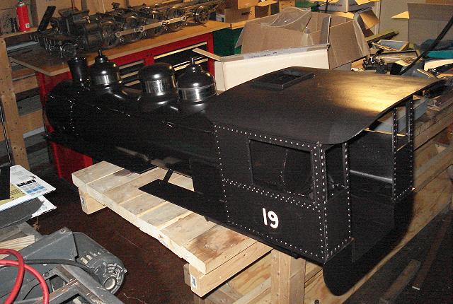
Image 125 -- Painting the Boiler and Cab And I really like this paint. In the bright sunlight it has sort or a bronzish color. It's really Black. But it's called Barbeque Grill Paint. It's good to over 1000 degrees Farenheit. It's neither quick to run or orange peel. It goes on nice with an airbrush. 11/9/7 -- More Side Rod work Several things were done here. Some you can see, some you can not. First, the rods were reduced in size to closer match the dimensions of the original drawing. The ends of the individual rod segments were rounded to match the prototype. Rod pins were made to replace the bolts that were holding the rod assemblies together. 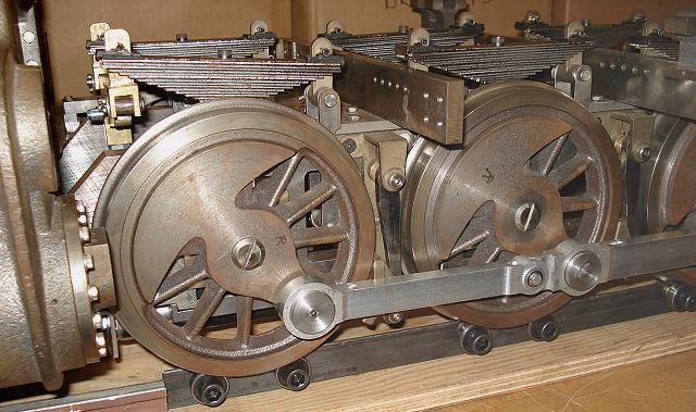
Image 127 -- Left Side Rod - front The rod pins load from the back. In this photos, you can see the rod pins held on with a flat washer and a push-on retaining ring. Also shown are the crankpin end rod bearing retainer caps and the screws holding them on. The #1 crank pins use setscrews due to limited clearance with the piston crosshead (not installed yet). 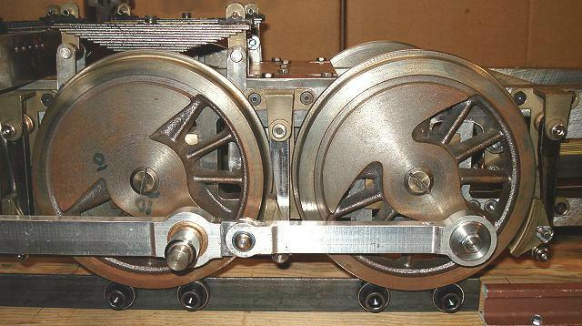
Image 128 -- Left Side Rod - rear As promised, what you can't see are the spacers between the wheels and the rod bearings, and the retainer caps and the rod bearings. These are fairly well hidden. The retainer caps were designed to hide the rode-end style bearings, which did not exist on a prototype locomotive.
TreadmillDid anyone notice my treadmill? The wheels of the locomotive are riding on ball bearings. This allows me to operate the locomotive without it going anywhere. It also allows me to turn the entire unit around without help from anyone else.On to Page 23 |