90 Ton Mikado, Page 23(Back to Page 22) 12/12/7 Valve and Piston WorkIt's time to get the left side of the locomotive running on air. (Yes you only need one cylinder to make it run.) Once completed, I'll go back and work on the other side.Piston and RodThe first task was to get the left side piston, rod, and slide working properly. I had to turn the piston casting down to the correct dimensions and drill it according to drawings. Then, likewise, make the leftside piston rod. Since I threaded my crossheads, I have to also thread one end of the piston rod. This is hard work and must be precise.Cross Slide and BracketThe cross slide is an assembly I built some time ago. Mounting it is difficult because both ends of it must be positioned precisely, both vertically and laterally. I find myself using shims under the cylinder end of the slide, and the crosshead slide bracket that supports the back end of the slide is a trim to fit part.Left Main RodHere's another part I made some time ago. I needed to make some shape adjustments to the left side main rod so it would fit up inside the crosshead. I still need to do some shaping to the crank end, add oil holes, and make spacers for the #3 crank pins.Reverse Shaft and ArmsThe reverse shaft runs the entire width of the engine and in fact is the widest part at 15.5 inches. My son Doug is always leaving his rocket junk here, so I just grabbed one of his 1/2" launch rods, cleaned it up a little, and used it for the reverse shaft.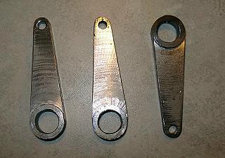
Image 129 -- Reverse Shaft Arms Three lever arms are needed - one to operate the reverse link on each side, and one on the right side to connect to the Johnson Bar in the cab via a control rod. Return CranksOut on the end of the #3 crank pins sits a return crank. It's job is to create a 90 degree lead from the main rods and drive the valve gear.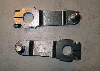
Image 130 -- Return Cranks and Crank Pins The eccentric rod connects to the crank pin with a hat bushing, a flat washer, and a castle nut. Eccentric Rods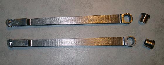
Image 131 -- Eccentric Rods and Hat Bushings This small rod connects the return crank to the reverse link. It includes a bronze bushing (bearing). Both parts need oil holes which are not shown on the drawings. Combination LeverThe purpose of the combination lever is to combine the motion of return crank with some motion from the crosshead. This generates a little phase lead to the valve to get it to operate slightly ahead of the pistons - both in forward and reverse.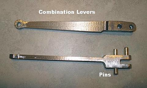
Image 132 -- Combination Levers and Pins Two captive brass pins are used to connect the upper end of the combination lever to the valve crosshead and to the radius rod. Radius RodsThe Radius Rod transmits the motion from the reverse link to the valves via the combination lever. The reverse link has a slot where a die block is positioned to operate the radius rod. The die block's position within the reverse link is controlled by the reverse shaft.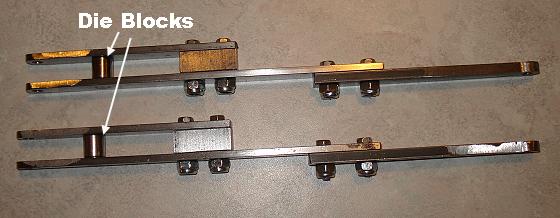
Image 133 -- Radius Rod Assemblies These nuts are huge, but they were all I had. I ordered nuts that are the right size. They should get here tomorrow. Lifting Links and Union LinksSimilar - but very different.A lifting link connects the reverse shaft arm on each side to the end of the radius rod. This controls the position of the die block relative to the reverse link and allows the locomotive engineer to control both the amount and direction of valve travel with the Johnson Bar in the cab. 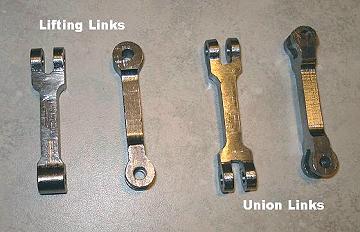
Image 134 -- Lifting Links and Union Links The union link connects the bottom end of the combination lever to the drop link on the piston crosshead. Now for a recap... 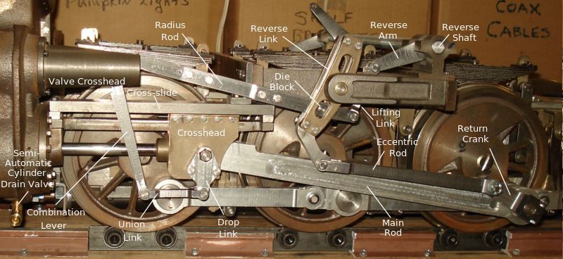
Image 137 -- Left Side Valve Gear Ready to Run
12/29/7 Steam DomeOne of the items on my "Loose Ends List" is to find a way to securely attach my steam dome to it's base. We don't want to be like Gordon and have it fly off and land in a ditch.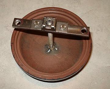
Image 138 -- Attaching Steam Dome to it's Base I welded a bolt to the inside top of the steam dome (and it didn't even bother the paint). Then I built this bracket to hold it to the base.
1/8/8 Leftside Running on AirI finally got my Mikado chassis running on air - the left side that is. Still have some things to work out. Valve timing isn't right in reverse, but I'll get that taken care of in a day or so. 
Image 139 -- Left SIde Running on Air (It's best to wait for all the frames to load then the video is smoother). (On to Page 24) |